UG-001
COLLAPSE DISPLAY BUTTON 
SETTINGS
BUTTON
07782-023
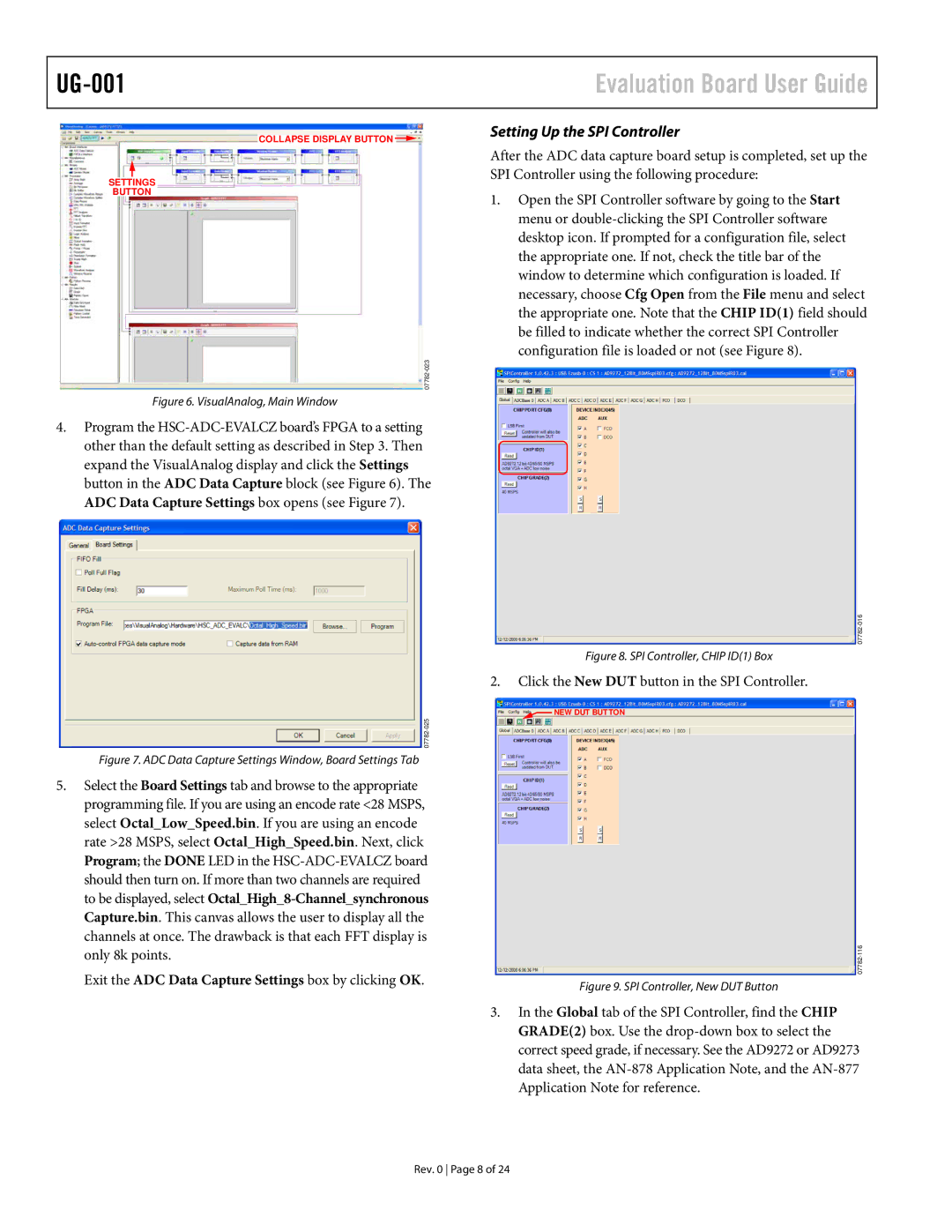
Figure 6. VisualAnalog, Main Window
4.Program the HSC-ADC-EVALCZ board’s FPGA to a setting other than the default setting as described in Step 3. Then expand the VisualAnalog display and click the Settings button in the ADC Data Capture block (see Figure 6). The ADC Data Capture Settings box opens (see Figure 7).
07782-025
Figure 7. ADC Data Capture Settings Window, Board Settings Tab
5.Select the Board Settings tab and browse to the appropriate programming file. If you are using an encode rate <28 MSPS, select Octal_Low_Speed.bin. If you are using an encode rate >28 MSPS, select Octal_High_Speed.bin. Next, click Program; the DONE LED in the HSC-ADC-EVALCZ board should then turn on. If more than two channels are required to be displayed, select Octal_High_8-Channel_synchronous Capture.bin. This canvas allows the user to display all the channels at once. The drawback is that each FFT display is only 8k points.
Exit the ADC Data Capture Settings box by clicking OK.
Evaluation Board User Guide
Setting Up the SPI Controller
After the ADC data capture board setup is completed, set up the SPI Controller using the following procedure:
1.Open the SPI Controller software by going to the Start menu or double-clicking the SPI Controller software desktop icon. If prompted for a configuration file, select the appropriate one. If not, check the title bar of the window to determine which configuration is loaded. If necessary, choose Cfg Open from the File menu and select the appropriate one. Note that the CHIP ID(1) field should be filled to indicate whether the correct SPI Controller configuration file is loaded or not (see Figure 8).
07782-016
Figure 8. SPI Controller, CHIP ID(1) Box
2.Click the New DUT button in the SPI Controller.
 NEW DUT BUTTON
07782-116
Figure 9. SPI Controller, New DUT Button
3.In the Global tab of the SPI Controller, find the CHIP GRADE(2) box. Use the drop-down box to select the correct speed grade, if necessary. See the AD9272 or AD9273 data sheet, the AN-878 Application Note, and the AN-877 Application Note for reference.