Contents
Features
Typical Measurement Setup
Equipment Needed
Documents Needed
Table of Contents
Input Signals
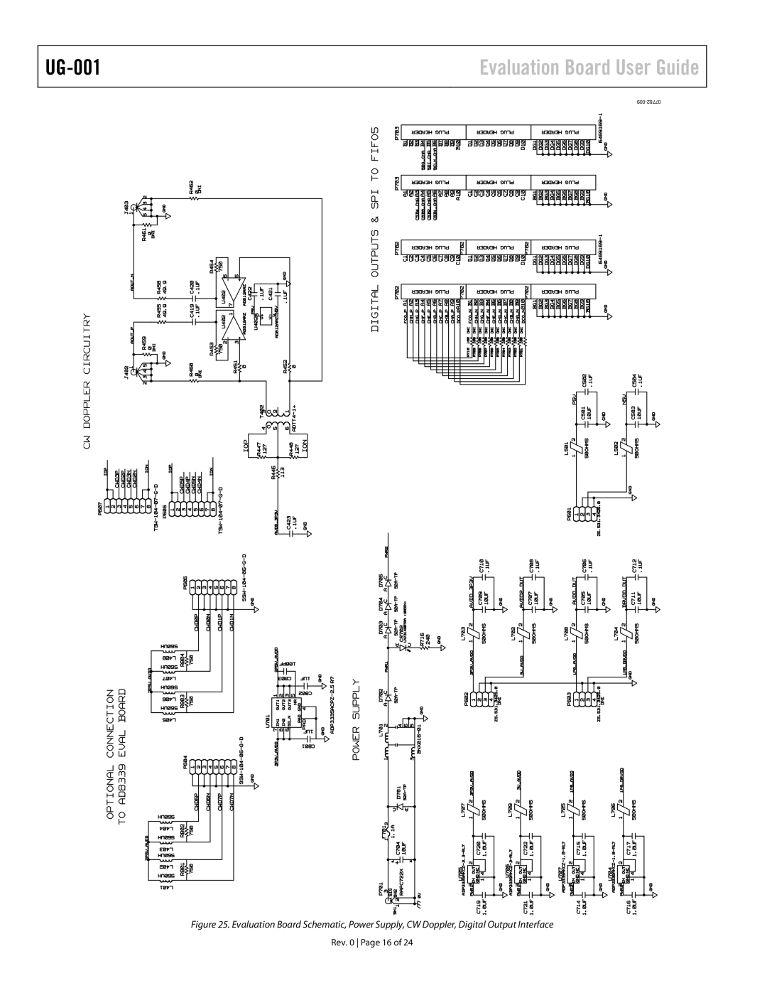
Power Supplies
Output Signals
Evaluation Board Connection
Default Operation Jumper Selection Settings
DOUTx+, DOUTx−
Evaluation Board Software Quick Start Procedures
Configuring the Board
Using the Software for Testing
Setting Up the ADC Data Capture Block
Setting Up the SPI Controller
VisualAnalog, Main Window
Click the Run button in the VisualAnalog toolbar
Using the Integrated Crosspoint Switch CW Doppler Mode
Adjusting the Amplitude of the Input Signal
SPI Controller, MODES8 Box
Evaluation Board Schematics and Artwork
Evaluation Board Schematic, DUT Analog Input Circuits
Rev Page 13
Evaluation Board Schematic, DUT, VREF, and Decoupling
Evaluation Board Schematic, Clock, SPI, and Gain Circuits
Rev Page 16
Evaluation Board User Guide
Evaluation Board Layout, Ground Plane Layer
Evaluation Board Layout, Power Plane Layer
Rev Page 20
Rev Page 21
Evaluation Board Layout, Bottom Side
Ordering Information
Bill of Materials
ESD Caution
ERJ-2RKF1240X