CONNECTING THE POWER AND LED
1.Connect the
2.Connect the Reset switch (labeled RESET SW) to your motherboard at the RST connector. Make sure the label always faces the front of the case.
3.Power LED (labeled POWER LED) connector is located behind the Reset connector.
4.Power Switch (labeled POWER SW) connects to the PWR connector on the motherboard.
5.Speaker (labeled SPEAKER) connector is behind the PWR connector.
6.Hard Drive LED (labeled HDD) connects to the IDE connector.
7.LED I, LED II connectors: This case comes with two extra LEDs, marked I, II. You may use these LED for various purposes such as SC SI LED, Message LED, etc.
CONNECTING THE USB PORTS
You will find a single
Note: Please check your motherboard manual for your USB header pin layout and make sure it matches the attached table. If it does not match this Intel standard, please call Antec customer service at (800) 22ANTEC (North America) or +31 (0) 10
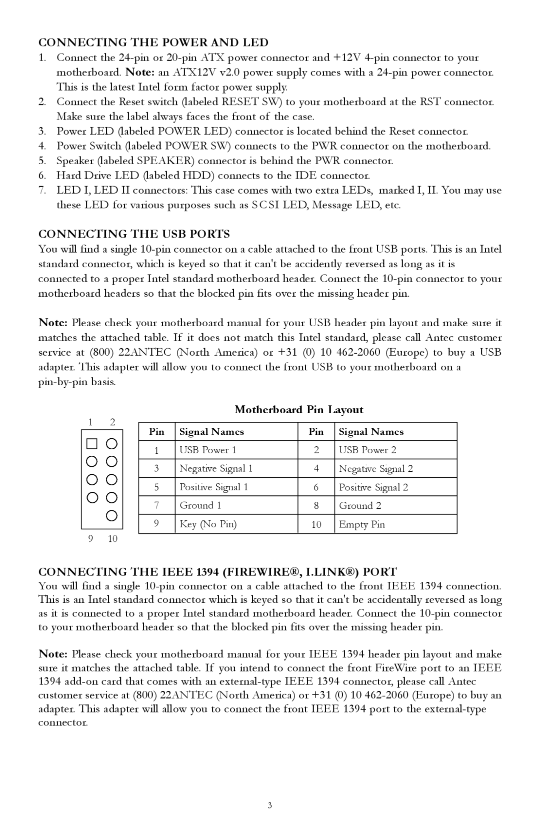
Motherboard Pin Layout
1 | 2 |
|
|
|
|
| |
Pin | Signal Names | Pin | Signal Names | ||||
|
|
| |||||
|
|
|
|
|
|
| |
|
|
| 1 | USB Power 1 | 2 | USB Power 2 | |
|
|
| 3 | Negative Signal 1 | 4 | Negative Signal 2 | |
|
|
|
|
|
|
| |
|
|
| 5 | Positive Signal 1 | 6 | Positive Signal 2 | |
|
|
| 7 | Ground 1 | 8 | Ground 2 | |
|
|
| 9 | Key (No Pin) | 10 | Empty Pin | |
9 | 10 |
|
|
|
|
| |
|
|
|
|
CONNECTING THE IEEE 1394 (FIREWIRE®, I.LINK®) PORT
You will find a single
Note: Please check your motherboard manual for your IEEE 1394 header pin layout and make sure it matches the attached table. If you intend to connect the front FireWire port to an IEEE 1394
3