Although care has been taken to prevent sharp edges in your Antec case, we strongly recommend taking your time and the appropriate care when working with it. Hurried or careless motion and use of excessive force, particularly when you are working in areas you cannot see clearly, are but a few examples of activity that should be avoided. Please use reasonable precaution.
Setting Up
1.Take the case out of the box. Remove the Styrofoam and plastic bag.
2.Place the case upright with the power supply fan at the back facing you on a stable flat surface.
3.Remove the two thumbscrews that fasten the top cover onto the case. These are the only screws you need to remove to open the case. Set these screws aside and keep them separate from the other screws.
4.Slide the top panel toward the rear of the case and lift it up to remove.
5.At the top of the each side panel, in front of the power supply, there is a 4” wide tab. Using this, lift and pull the side panels out to remove.
6.Inside the case you should see the power supply, some wiring (LED’s, etc.), an installed I/O panel, a power cord and a plastic bag containing more hardware (screws, brass standoff, plastic stands, etc.).
Motherboard Installation
This manual is not designed to cover CPU, RAM, or expansion card installation. Please consult the motherboard manual for specific mounting instructions and troubleshooting.
1.Lay the case down so that the open side is up. You should be able to see the drive cage and power supply.
2.Make sure you have the appropriate I/O panel for the motherboard. If the panel provided is not suitable for the motherboard, please contact the motherboard manufacturer for the correct I/O panel.
3.Line up the motherboard with the standoff holes, and determine which ones line up and remember where they are. Not all motherboards will match with all of the provided screw holes, and this is not necessary for proper functionality.) Some standoffs may be
4.Lift up and remove the motherboard.
5.Screw in the brass standoffs to the threaded holes that line up with the moth- erboard.
6.Place the motherboard on the brass standoffs.
7.Screw in the motherboard to the standoffs with the provided
8.The motherboard is now installed.
Connecting the Power and LED
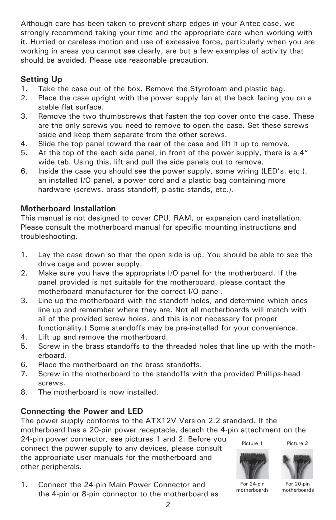
The power supply conforms to the ATX12V Version 2.2 standard. If the motherboard has a
Picture 1 | Picture 2 | ||
connect the power supply to any devices, please consult | |||
|
| ||
the appropriate user manuals for the motherboard and |
|
| |
other peripherals. |
|
| |
1. Connect the | For | For | |
the | motherboards | motherboards | |
|
|
2