needed. If the motherboard uses a
2.Connect the Reset switch (labeled RESET SW) to the motherboard at the RST connector. Polarity (positive and negative) does not matter for switches.
3.Power Switch (labeled POWER SW) connects to the PWR connector on the motherboard.
4.Power LED (labeled POWER LED) connector is located behind the Reset connector. For LEDs, the colored wire is positive (+) and the white wire is negative
5.Hard Drive LED (labeled H.D.D. LED) connects to the IDE connector.
USB Connection
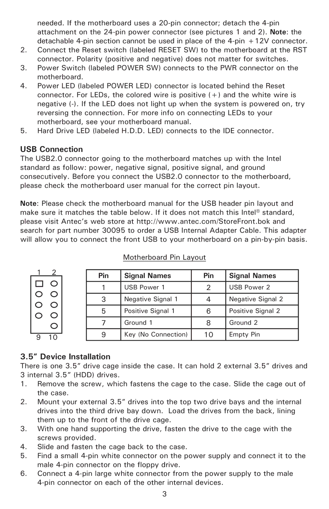
The USB2.0 connector going to the motherboard matches up with the Intel standard as follow: power, negative signal, positive signal, and ground consecutively. Before you connect the USB2.0 connector to the motherboard, please check the motherboard user manual for the correct pin layout.
Note: Please check the motherboard manual for the USB header pin layout and make sure it matches the table below. If it does not match this Intel® standard, please visit Antec’s web store at http://www.antec.com/StoreFront.bok and search for part number 30095 to order a USB Internal Adapter Cable. This adapter will allow you to connect the front USB to your motherboard on a
|
|
| Motherboard Pin Layout |
| ||
1 | 2 |
|
|
|
| |
Pin | Signal Names | Pin | Signal Names | |||
|
| |||||
|
|
|
|
|
| |
|
| 1 | USB Power 1 | 2 | USB Power 2 | |
|
| 3 | Negative Signal 1 | 4 | Negative Signal 2 | |
|
| 5 | Positive Signal 1 | 6 | Positive Signal 2 | |
|
| 7 | Ground 1 | 8 | Ground 2 | |
|
|
|
|
|
| |
9 | 10 | 9 | Key (No Connection) | 10 | Empty Pin | |
|
|
|
| |||
3.5” Device Installation
There is one 3.5” drive cage inside the case. It can hold 2 external 3.5” drives and 3 internal 3.5” (HDD) drives.
1.Remove the screw, which fastens the cage to the case. Slide the cage out of the case.
2.Mount your external 3.5” drives into the top two drive bays and the internal drives into the third drive bay down. Load the drives from the back, lining them up to the front of the drive cage.
3.With one hand supporting the drive, fasten the drive to the cage with the screws provided.
4.Slide and fasten the cage back to the case.
5.Find a small
6.Connect a
3