1.Make sure you have the correct I/O panel for your motherboard. If the panel provided with the case isn’t suitable, please contact your motherboard manufacturer for the correct I/O panel.

2.Line up your motherboard with the standoff holes, and remember which holes are lined up. Not all motherboards will match with all the provided holes; this is normal, and won’t affect functionality. (In other words, there will likely be extra holes.)

3.Remove your motherboard by lifting it up.

4.Screw the brass standoffs into the threaded holes that line up with your motherboard. Do not over-tighten the standoffs. Some standoffs may be pre-installed for your convenience.

5.Place your motherboard on the brass standoffs.

6.Fasten your motherboard to the standoffs with the provided Philips-head screws. Your motherboard is now installed.

Connecting the Front I/O

1.Connect the Reset switch (labeled RESET SW) to the motherboard at the RST connector. Polarity (positive and negative) does not matter for switches.

2.Power Switch (labeled POWER SW) connects to the PWR connector on the motherboard.

3.Connect the Power LED (labeled POWER LED) to your motherboard. For LEDs, colored wires are positive (+). White or black wires are negative

(–). If the LED does not light up when the system is powered on, try reversing the connection. For more info on connecting LEDs to your motherboard, see your motherboard manual.

4.Hard Drive LED (labeled HDD LED) connects to the hard drive activity header.

Connecting the USB Ports

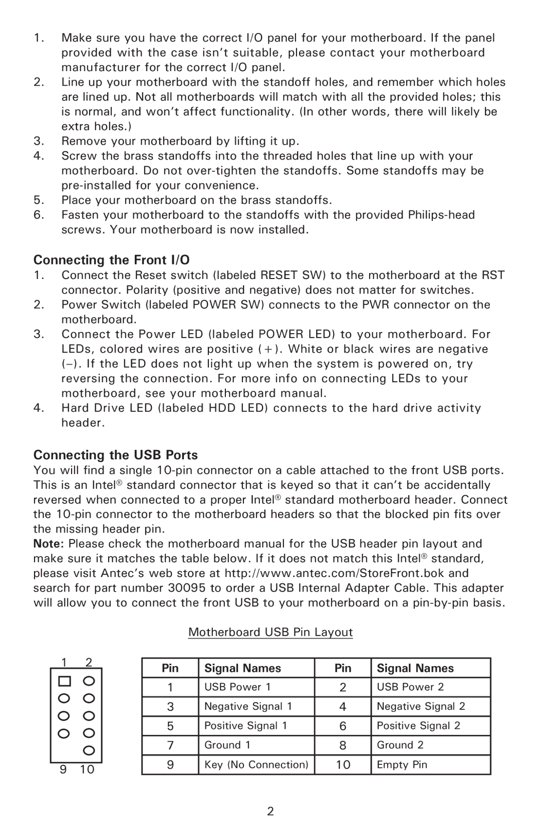
You will find a single 10-pin connector on a cable attached to the front USB ports. This is an Intel® standard connector that is keyed so that it can’t be accidentally reversed when connected to a proper Intel® standard motherboard header. Connect the 10-pin connector to the motherboard headers so that the blocked pin fits over the missing header pin.

Note: Please check the motherboard manual for the USB header pin layout and make sure it matches the table below. If it does not match this Intel® standard, please visit Antec’s web store at http://www.antec.com/StoreFront.bok and search for part number 30095 to order a USB Internal Adapter Cable. This adapter will allow you to connect the front USB to your motherboard on a pin-by-pin basis.

Motherboard USB Pin Layout

1

2

Pin

Signal Names

Pin

Signal Names


1

USB Power 1

2

USB Power 2


3

Negative Signal 1

4

Negative Signal 2


5

Positive Signal 1

6

Positive Signal 2


7

Ground 1

8

Ground 2

9

10

9

Key (No Connection)

10

Empty Pin


2

Page 3
Image 3
Antec Plus 550, Solo White, Designer 500 user manual Connecting the Front I/O, Connecting the USB Ports

Designer 500, Solo White, Plus 550 specifications

Antec, a leading manufacturer of PC components, has continued to innovate and impress with its latest offerings in the PC case market. Among their standout products are the Antec Plus 550, Designer 500, and Solo White. Each of these cases brings a unique combination of features, technologies, and design aesthetics tailored to meet the needs of gamers and PC builders alike.

The Antec Plus 550 is a versatile mid-tower case that balances functionality and efficiency perfectly. It supports a wide range of motherboards, from mini-ITX to ATX, ensuring compatibility for various system builds. One of its standout features is the excellent airflow, which is achieved through mesh front panels and multiple cooling options. Users can install up to six fans, which allows for optimized thermal performance, essential for gaming rigs and high-performance systems. The Plus 550 also offers ample storage options with dedicated spaces for multiple SSDs and HDDs, showcasing Antec's focus on practicality.

Next, the Antec Designer 500 combines elegant aesthetics with practical features. Its sleek design includes a tempered glass side panel that showcases the internal components and RGB lighting, appealing to users who value aesthetics alongside performance. The Designer 500 supports ATX and micro-ATX motherboards and features efficient cable management systems, making it easy to build a tidy and organized setup. Furthermore, the case is equipped with advanced cooling system options, including support for liquid cooling setups, ensuring that even the most demanding systems remain cool under load.

Lastly, the Solo White case is a showcase of minimalistic design and functional architecture. As the name suggests, its clean white exterior complements any setup while offering a unique touch. The Solo White also features a modular design, allowing for easy customization and upgrades. Its efficient airflow design is combined with dust filters to ensure that the system remains clean and well-ventilated, prolonging the life of the internal components. Additionally, it supports high-end graphics cards and multiple storage solutions, catering to both gamers and content creators.

In summary, Antec's Plus 550, Designer 500, and Solo White cases exemplify the brand's commitment to quality, functionality, and user-focused design. With features such as excellent airflow, efficient cooling options, and customizable aesthetics, these cases provide everything users need for a solid and attractive PC build. Whether for gaming or professional use, Antec’s innovation continues to push the boundaries in the world of PC cases.