the
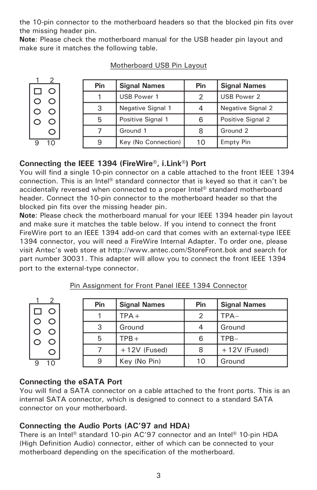
Note: Please check the motherboard manual for the USB header pin layout and make sure it matches the following table.
|
|
| Motherboard USB Pin Layout |
| ||
1 | 2 |
|
|
|
|
|
Pin |
| Signal Names | Pin | Signal Names | ||
|
|
| ||||
|
|
|
|
|
|
|
|
| 1 |
| USB Power 1 | 2 | USB Power 2 |
|
|
|
|
|
|
|
|
| 3 |
| Negative Signal 1 | 4 | Negative Signal 2 |
|
|
|
|
|
|
|
|
| 5 |
| Positive Signal 1 | 6 | Positive Signal 2 |
|
|
|
|
|
|
|
|
| 7 |
| Ground 1 | 8 | Ground 2 |
|
|
|
|
|
|
|
9 | 10 | 9 |
| Key (No Connection) | 10 | Empty Pin |
Connecting the IEEE 1394 (FireWire®, i.Link®) Port
You will find a single
Note: Please check the motherboard manual for your IEEE 1394 header pin layout and make sure it matches the table below. If you intend to connect the front FireWire port to an IEEE 1394
|
| Pin Assignment for Front Panel IEEE 1394 Connector | ||||
1 | 2 |
|
|
|
|
|
| Pin | Signal Names | Pin | Signal Names | ||
|
|
| ||||
|
|
|
|
|
|
|
|
|
| 1 | TPA+ | 2 | TPA– |
|
|
|
|
|
|
|
|
|
| 3 | Ground | 4 | Ground |
|
|
| 5 | TPB+ | 6 | TPB– |
|
|
| 7 | +12V (Fused) | 8 | +12V (Fused) |
9 | 10 |
| 9 | Key (No Pin) | 10 | Ground |
Connecting the eSATA Port
You will find a SATA connector on a cable attached to the front ports. This is an internal SATA connector, which is designed to connect to a standard SATA connector on your motherboard.
Connecting the Audio Ports (AC’97 and HDA)
There is an Intel® standard
3