H E AT C O N T R O L L E R , I N C . WAT E R - S O U R C E H E AT P U M P S
R e s i d e n t i a l S p l i t - 6 0 H z R 2 2 & R 4 1 0 A
R e v. : 5 J u n e , 2 0 0 8
Electrical - Line Voltage
ELECTRICAL - POWER WIRING
Electrical - Line Voltage
All field installed wiring, including electrical ground, must comply with the National Electrical Code as well as all applicable local codes. Refer to the unit electrical data for fuse sizes. Consult wiring diagram for field connections that must be made by the installing (or electrical) contractor.
All final electrical connections must be made with a length of flexible conduit to minimize vibration and sound transmission to the building.
General Line Voltage Wiring
Be sure the available power is the same voltage and phase shown on the unit serial plate. Line and low voltage wiring must be done in accordance with local codes or the National Electric Code, whichever is applicable.
Power Connection
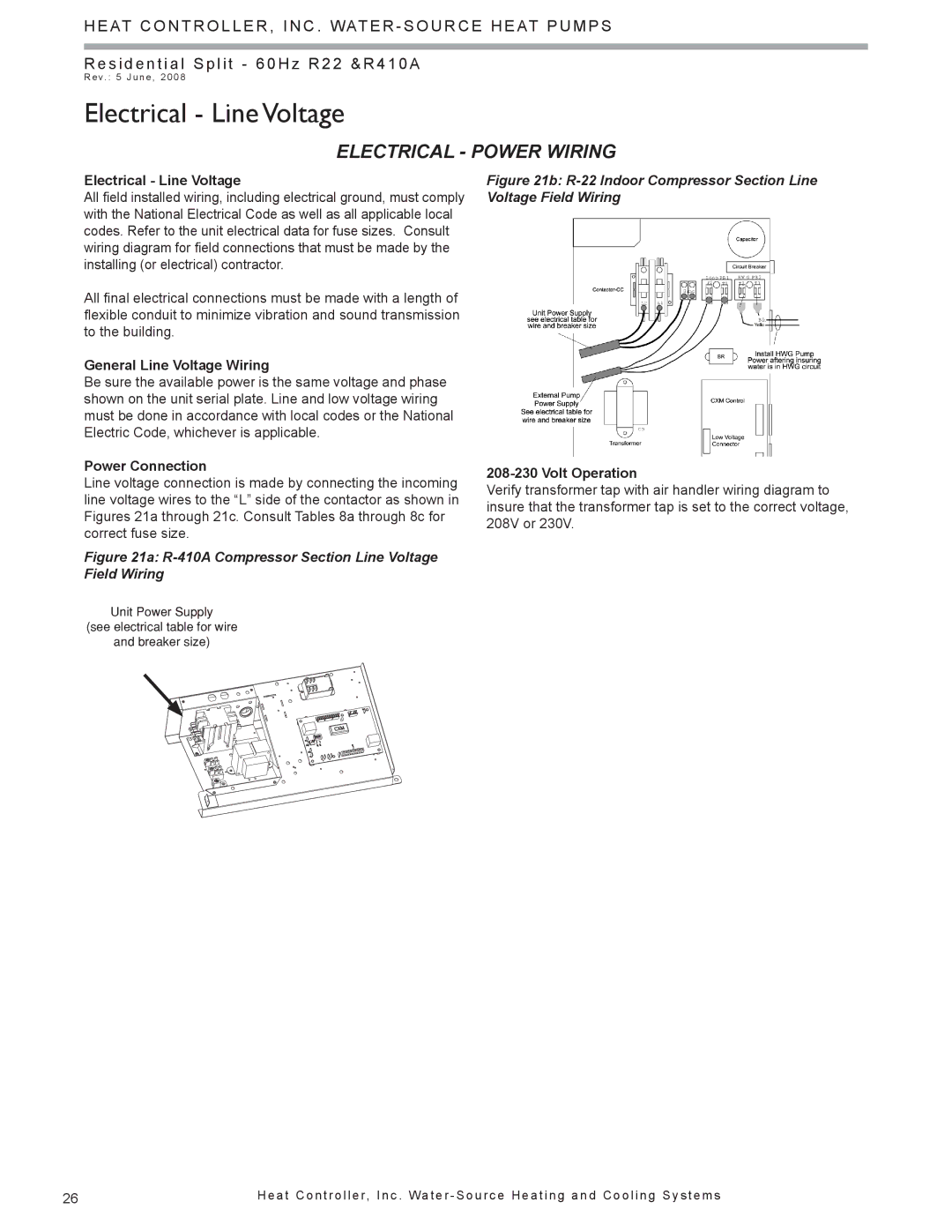
Line voltage connection is made by connecting the incoming line voltage wires to the “L” side of the contactor as shown in Figures 21a through 21c. Consult Tables 8a through 8c for correct fuse size.
Figure 21a: R-410A Compressor Section Line Voltage Field Wiring
Unit Power Supply
(see electrical table for wire
and breaker size)
Figure 21b: R-22 Indoor Compressor Section Line Voltage Field Wiring
208-230 Volt Operation
Verify transformer tap with air handler wiring diagram to insure that the transformer tap is set to the correct voltage, 208V or 230V.
26 | H e a t C o n t r o l l e r, I n c . Wa t e r - S o u r c e H e a t i n g a n d C o o l i n g S y s t e m s |