Heat Controller HTS SERIES SPLIT SYSTEM, HSS manual Installation, External Flow Controller Mounting

Models: HSS HTS SERIES SPLIT SYSTEM

1 48
Download 48 pages 27.01 Kb
Page 10
Image 10
External Flow Controller Mounting

H E AT C O N T R O L L E R , I N C . WAT E R - S O U R C E H E AT P U M P S

R e s i d e n t i a l S p l i t - 6 0 H z R 2 2 & R 4 1 0 A

R e v. : 5 J u n e , 2 0 0 8

Installation

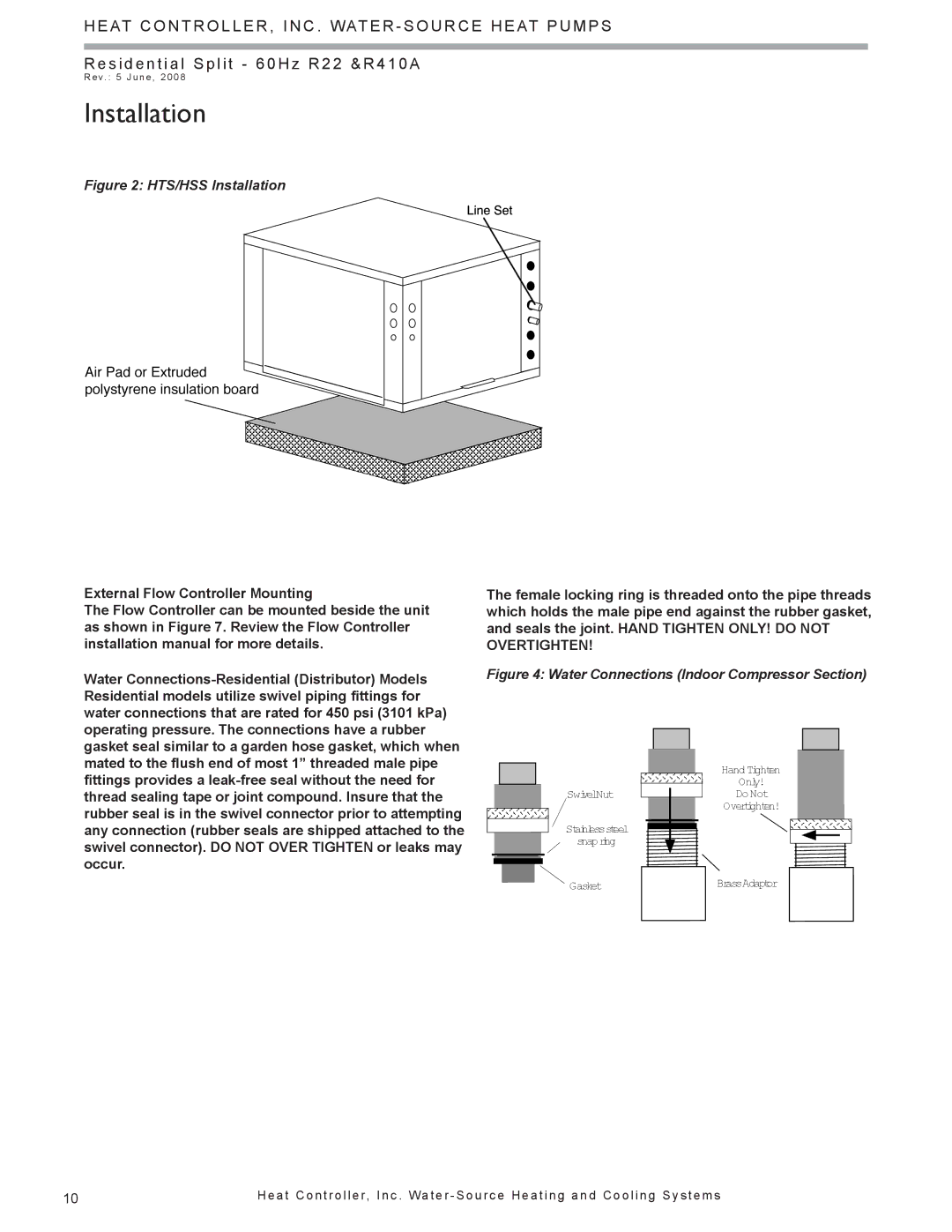
Figure 2: HTS/HSS Installation

External Flow Controller Mounting

The Flow Controller can be mounted beside the unit as shown in Figure 7. Review the Flow Controller installation manual for more details.

Water Connections-Residential (Distributor) Models Residential models utilize swivel piping fittings for water connections that are rated for 450 psi (3101 kPa) operating pressure. The connections have a rubber gasket seal similar to a garden hose gasket, which when mated to the flush end of most 1” threaded male pipe fittings provides a leak-free seal without the need for thread sealing tape or joint compound. Insure that the rubber seal is in the swivel connector prior to attempting any connection (rubber seals are shipped attached to the swivel connector). DO NOT OVER TIGHTEN or leaks may occur.

The female locking ring is threaded onto the pipe threads which holds the male pipe end against the rubber gasket, and seals the joint. HAND TIGHTEN ONLY! DO NOT OVERTIGHTEN!

Figure 4: Water Connections (Indoor Compressor Section)

Hand Tighten

Only!

SwivelNutDo Not

Overtighten!

Stainlesssteel snapring

GasketBrassAdaptor

10

H e a t C o n t r o l l e r, I n c . Wa t e r - S o u r c e H e a t i n g a n d C o o l i n g S y s t e m s

Page 10
Image 10
Heat Controller HTS SERIES SPLIT SYSTEM, HSS manual Installation, External Flow Controller Mounting