H E AT C O N T R O L L E R , I N C . WAT E R - S O U R C E H E AT P U M P S
R e s i d e n t i a l S p l i t - 6 0 H z R 2 2 & R 4 1 0 A
R e v. : 5 J u n e , 2 0 0 8
Unit Operating Conditions
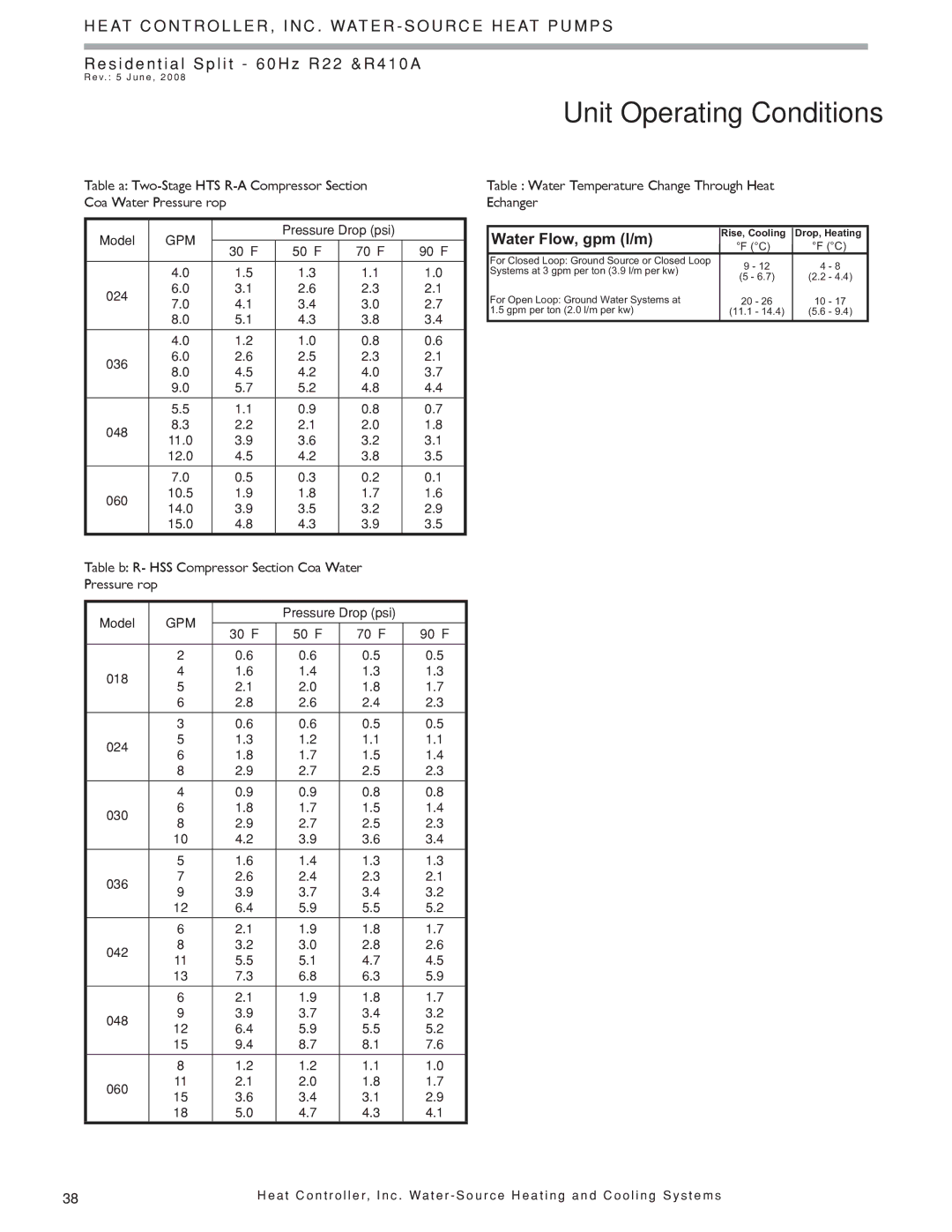
Table 12a:
Model | GPM |
| Pressure Drop (psi) |
| ||
|
|
|
| |||
30°F | 50°F | 70°F | 90°F | |||
|
| |||||
|
|
|
|
|
| |
| 4.0 | 1.5 | 1.3 | 1.1 | 1.0 | |
024 | 6.0 | 3.1 | 2.6 | 2.3 | 2.1 | |
7.0 | 4.1 | 3.4 | 3.0 | 2.7 | ||
| ||||||
| 8.0 | 5.1 | 4.3 | 3.8 | 3.4 | |
|
|
|
|
|
| |
| 4.0 | 1.2 | 1.0 | 0.8 | 0.6 | |
036 | 6.0 | 2.6 | 2.5 | 2.3 | 2.1 | |
8.0 | 4.5 | 4.2 | 4.0 | 3.7 | ||
| ||||||
| 9.0 | 5.7 | 5.2 | 4.8 | 4.4 | |
|
|
|
|
|
| |
| 5.5 | 1.1 | 0.9 | 0.8 | 0.7 | |
048 | 8.3 | 2.2 | 2.1 | 2.0 | 1.8 | |
11.0 | 3.9 | 3.6 | 3.2 | 3.1 | ||
| ||||||
| 12.0 | 4.5 | 4.2 | 3.8 | 3.5 | |
|
|
|
|
|
| |
| 7.0 | 0.5 | 0.3 | 0.2 | 0.1 | |
060 | 10.5 | 1.9 | 1.8 | 1.7 | 1.6 | |
14.0 | 3.9 | 3.5 | 3.2 | 2.9 | ||
| ||||||
| 15.0 | 4.8 | 4.3 | 3.9 | 3.5 | |
|
|
|
|
|
| |
Table 12b: R-22 HSS Compressor Section Coax Water Pressure Drop
Model | GPM |
| Pressure Drop (psi) |
| ||
|
|
|
| |||
30°F | 50°F | 70°F | 90°F | |||
|
| |||||
|
|
|
|
|
| |
| 2 | 0.6 | 0.6 | 0.5 | 0.5 | |
018 | 4 | 1.6 | 1.4 | 1.3 | 1.3 | |
5 | 2.1 | 2.0 | 1.8 | 1.7 | ||
| ||||||
| 6 | 2.8 | 2.6 | 2.4 | 2.3 | |
|
|
|
|
|
| |
| 3 | 0.6 | 0.6 | 0.5 | 0.5 | |
024 | 5 | 1.3 | 1.2 | 1.1 | 1.1 | |
6 | 1.8 | 1.7 | 1.5 | 1.4 | ||
| ||||||
| 8 | 2.9 | 2.7 | 2.5 | 2.3 | |
|
|
|
|
|
| |
| 4 | 0.9 | 0.9 | 0.8 | 0.8 | |
030 | 6 | 1.8 | 1.7 | 1.5 | 1.4 | |
8 | 2.9 | 2.7 | 2.5 | 2.3 | ||
| ||||||
| 10 | 4.2 | 3.9 | 3.6 | 3.4 | |
|
|
|
|
|
| |
| 5 | 1.6 | 1.4 | 1.3 | 1.3 | |
036 | 7 | 2.6 | 2.4 | 2.3 | 2.1 | |
9 | 3.9 | 3.7 | 3.4 | 3.2 | ||
| ||||||
| 12 | 6.4 | 5.9 | 5.5 | 5.2 | |
|
|
|
|
|
| |
| 6 | 2.1 | 1.9 | 1.8 | 1.7 | |
042 | 8 | 3.2 | 3.0 | 2.8 | 2.6 | |
11 | 5.5 | 5.1 | 4.7 | 4.5 | ||
| ||||||
| 13 | 7.3 | 6.8 | 6.3 | 5.9 | |
|
|
|
|
|
| |
| 6 | 2.1 | 1.9 | 1.8 | 1.7 | |
048 | 9 | 3.9 | 3.7 | 3.4 | 3.2 | |
12 | 6.4 | 5.9 | 5.5 | 5.2 | ||
| ||||||
| 15 | 9.4 | 8.7 | 8.1 | 7.6 | |
|
|
|
|
|
| |
| 8 | 1.2 | 1.2 | 1.1 | 1.0 | |
060 | 11 | 2.1 | 2.0 | 1.8 | 1.7 | |
15 | 3.6 | 3.4 | 3.1 | 2.9 | ||
| ||||||
| 18 | 5.0 | 4.7 | 4.3 | 4.1 | |
Table 13: Water Temperature Change Through Heat Exchanger
��������������������� | ������������� | ������������� |
| ������� | |
| ������� | |
��������������������������������������������� |
| ����� |
����������������������������������������� | ������ | |
| ����������� | |
| ��������� | |
�������������������������������������� | ������� | ������� |
�������������������������������� | ������������� | ����������� |
|
|
|
38 | H e a t C o n t r o l l e r, I n c . Wa t e r - S o u r c e H e a t i n g a n d C o o l i n g S y s t e m s |