T h e Q u a l i t y L e a d e r i n C o n d i t i o n i n g A i r
R e s i d e n t i a l S p l i t - 6 0 H z R 2 2 & R 4 1 0 A
R e v. : 5 J u n e , 2 0 0 8
Electrical - HWG Wiring
HWG Wiring - “Indoor” Compressor Section
The hot water generator pump power wiring is disabled at the factory to prevent operating the HWG pump “dry.” After all HWG piping is completed and air purged from the water piping, the pump power wires should be applied to terminals on the HWG power block PB2 as shown in the unit wiring diagram. This connection can also serve as a HWG disable when servicing the unit.
ELECTRICAL - LOW VOLTAGE WIRING
Thermostat Connections
The thermostat should be wired directly to the CXM board. Figures 22a through 22c show low voltage wiring. Note that the air handler or furnace transformer will be used to power the CXM board in the compressor section. See “Electrical – Thermostat” for specific terminal connections.
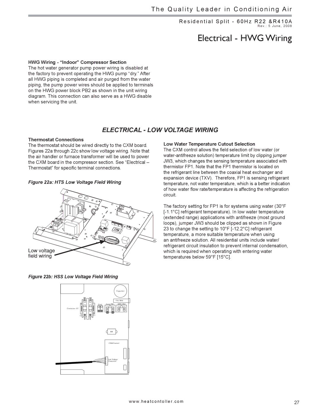
Figure 22a: HTS Low Voltage Field Wiring
Low voltage field wiring
Figure 22b: HSS Low Voltage Field Wiring
|
| C apacitor |
|
| Circ Brkr |
G rnd | Loop PB1 | HW G PB2 |
Low Water Temperature Cutout Selection
The CXM control allows the field selection of low water (or
The factory setting for FP1 is for systems using water (30°F
an antifreeze solution. All residential units include water/ refrigerant circuit insulation to prevent internal condensation, which is required when operating with entering water temperatures below 59°F [15°C].
L2
L1
BR
C XM Control
Low Voltage Connector
w w w. h e a t c o n t o l l e r. c o m | 27 |