T h e Q u a l i t y L e a d e r i n C o n d i t i o n i n g A i r
R e s i d e n t i a l S p l i t - 6 0 H z R 2 2 & R 4 1 0 A
R e v. : 5 J u n e , 2 0 0 8
Refrigeration Installation
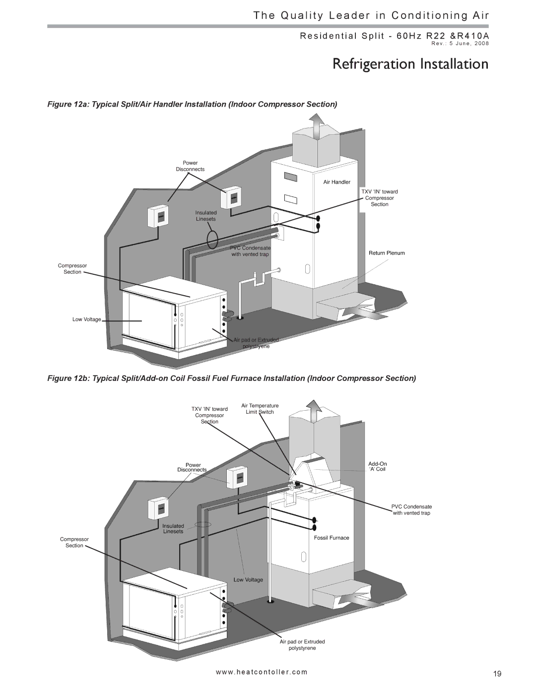
Figure 12a: Typical Split/Air Handler Installation (Indoor Compressor Section)
Power
Disconnects
Insulated
Linesets
PVC Condensate with vented trap
Compressor
Section
Low Voltage
![]() Air pad or Extruded polystryene
Air pad or Extruded polystryene
TXV 'IN' toward
Compressor
Section
Figure 12b: Typical Split/Add-on Coil Fossil Fuel Furnace Installation (Indoor Compressor Section)
Air Temperature
TXV 'IN' toward Limit Switch
Compressor
Section
PVC Condensate with vented trap
Compressor
Section
Air pad or Extruded
polystyrene
w w w. h e a t c o n t o l l e r. c o m | 19 |