H E AT C O N T R O L L E R , I N C . WAT E R - S O U R C E H E AT P U M P S
R e s i d e n t i a l S p l i t - 6 0 H z R 2 2 & R 4 1 0 A
R e v. : 5 J u n e , 2 0 0 8
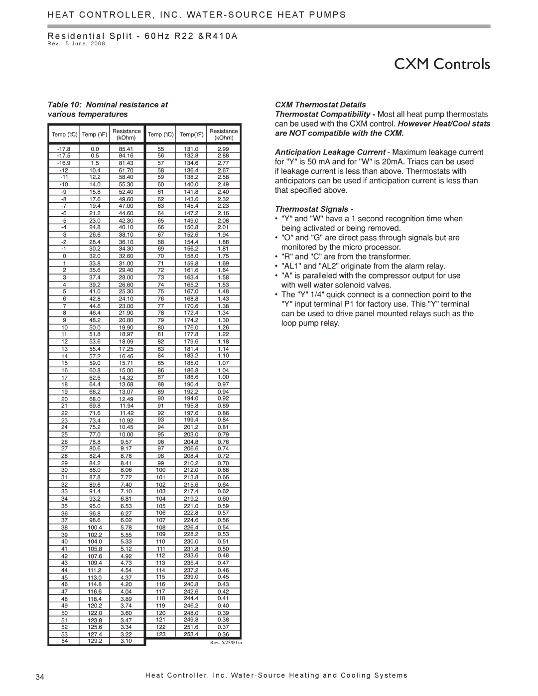
Table 10: Nominal resistance at various temperatures
ϒ | ϒ |
| ϒ | ϒ |
|
|
|
|
|
|
|
|
|
|
|
|
|
|
|
|
|
|
|
|
|
|
|
|
|
|
|
|
|
|
|
|
|
|
|
|
|
|
|
|
|
|
|
|
|
|
|
|
|
|
|
|
|
|
|
|
|
|
|
|
|
|
|
|
|
|
|
|
|
|
|
|
|
|
|
|
|
|
|
|
|
|
|
|
|
|
|
|
|
|
|
|
|
|
|
|
|
|
|
|
|
|
|
|
|
|
|
|
|
|
|
|
|
|
|
|
|
|
|
|
|
|
|
|
|
|
|
|
|
|
|
|
|
|
|
|
|
|
|
|
|
|
|
|
|
|
|
|
|
|
|
|
|
|
|
|
|
|
|
|
|
|
|
|
|
|
|
|
|
|
|
|
|
|
|
|
|
|
|
|
|
|
|
|
|
|
|
|
|
|
|
|
|
|
|
|
|
|
|
|
|
|
|
|
|
|
|
|
|
|
|
|
|
|
|
|
|
|
|
|
|
|
|
|
|
|
|
|
|
|
|
|
|
|
|
|
|
|
|
|
|
|
|
|
|
|
|
|
|
|
|
|
|
|
|
|
|
|
|
|
|
|
|
|
|
|
|
|
|
|
|
|
|
|
|
|
|
|
|
|
|
|
|
|
|
|
|
|
|
|
|
|
|
|
|
|
|
|
|
|
|
|
|
|
|
|
|
|
|
|
|
|
|
|
|
|
|
|
|
|
|
|
|
|
|
|
|
|
|
|
|
|
|
|
|
|
|
|
|
|
|
|
|
|
|
|
|
|
|
|
|
|
|
|
|
|
|
|
|
|
|
|
|
|
|
|
|
|
|
|
|
|
|
|
|
|
|
|
|
|
|
|
|
|
|
|
|
|
|
|
|
|
|
|
|
|
|
|
|
|
|
|
|
|
|
|
|
|
|
|
|
|
|
|
|
|
|
|
|
|
|
|
|
|
|
|
|
|
|
|
|
|
|
CXM Controls
CXM Thermostat Details
Thermostat Compatibility - Most all heat pump thermostats can be used with the CXM control. However Heat/Cool stats are NOT compatible with the CXM.
Anticipation Leakage Current - Maximum leakage current for "Y" is 50 mA and for "W" is 20mA. Triacs can be used if leakage current is less than above. Thermostats with anticipators can be used if anticipation current is less than that specified above.
Thermostat Signals -
•"Y" and "W" have a 1 second recognition time when being activated or being removed.
•"O" and "G" are direct pass through signals but are monitored by the micro processor.
•"R" and "C" are from the transformer.
•"AL1" and "AL2" originate from the alarm relay.
•"A" is paralleled with the compressor output for use with well water solenoid valves.
•The "Y" 1/4" quick connect is a connection point to the
"Y" input terminal P1 for factory use. This "Y" terminal can be used to drive panel mounted relays such as the loop pump relay.
34 | H e a t C o n t r o l l e r, I n c . Wa t e r - S o u r c e H e a t i n g a n d C o o l i n g S y s t e m s |
