T h e Q u a l i t y L e a d e r i n C o n d i t i o n i n g A i r
Hot Water Generator
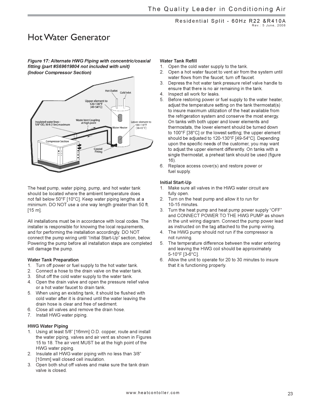
Figure 17: Alternate HWG Piping with concentric/coaxial fitting (part #S69619804 not included with unit)
(Indoor Compressor Section)
The heat pump, water piping, pump, and hot water tank should be located where the ambient temperature does not fall below 50°F [10°C]. Keep water piping lengths at a minimum. DO NOT use a one way length greater than 50 ft. [15 m].
All installations must be in accordance with local codes. The installer is responsible for knowing the local requirements, and for performing the installation accordingly. DO NOT connect the pump wiring until “Initial
Water Tank Preparation
1.Turn off power or fuel supply to the hot water tank.
2.Connect a hose to the drain valve on the water tank.
3.Shut off the cold water supply to the water tank.
4.Open the drain valve and open the pressure relief valve or a hot water faucet to drain tank.
5.When using an existing tank, it should be flushed with cold water after it is drained until the water leaving the drain hose is clear and free of sediment.
6.Close all valves and remove the drain hose.
7.Install HWG water piping.
HWG Water Piping
1.Using at least 5/8” [16mm] O.D. copper, route and install the water piping, valves and air vent as shown in Figures 15 to 18. The air vent MUST be at the high point of the
HWG water piping.
2.Insulate all HWG water piping with no less than 3/8” [10mm] wall closed cell insulation.
3.Open both shut off valves and make sure the tank drain valve is closed.
R e s i d e n t i a l S p l i t - 6 0 H z R 2 2 & R 4 1 0 A
R e v. : 5 J u n e , 2 0 0 8
Water Tank Refill
1.Open the cold water supply to the tank.
2.Open a hot water faucet to vent air from the system until water flows from the faucet; turn off faucet.
3.Depress the hot water tank pressure relief valve handle to ensure that there is no air remaining in the tank.
4.Inspect all work for leaks.
5.Before restoring power or fuel supply to the water heater, adjust the temperature setting on the tank thermostat(s) to insure maximum utilization of the heat available from the refrigeration system and conserve the most energy. On tanks with both upper and lower elements and thermostats, the lower element should be turned down to 100°F [38°C] or the lowest setting; the upper element should be adjusted to
6.Replace access cover(s) and restore power or fuel supply.
Initial Start-Up
1.Make sure all valves in the HWG water circuit are fully open.
2.Turn on the heat pump and allow it to run for
3.Turn the heat pump and heat pump power supply “OFF” and CONNECT POWER TO THE HWG PUMP as shown in the unit wiring diagram. Connect the pump power lead as instructed on the tag attached to the pump wiring.
4.The HWG pump should not run if the compressor is not running.
5.The temperature difference between the water entering and leaving the HWG coil should be approximately
6.Allow the unit to operate for 20 to 30 minutes to insure that it is functioning properly.
w w w. h e a t c o n t o l l e r. c o m | 23 |