H E AT C O N T R O L L E R , I N C . WAT E R - S O U R C E H E AT P U M P S
R e s i d e n t i a l S p l i t - 6 0 H z R 2 2 & R 4 1 0 A
R e v. : 5 J u n e , 2 0 0 8
Refrigeration Installation
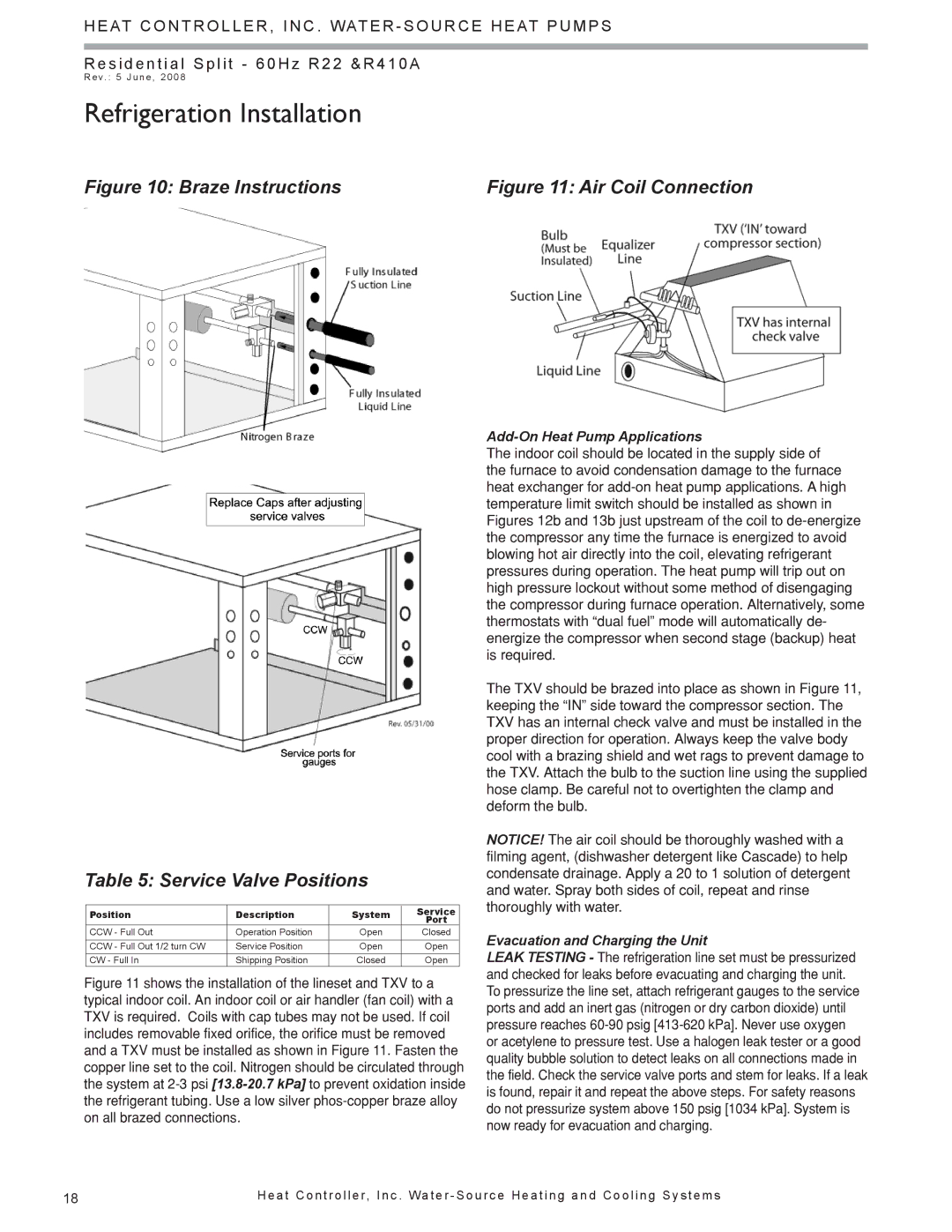
Figure 10: Braze Instructions | Figure 11: Air Coil Connection |
Table 5: Service Valve Positions
Position | Description | System | Service | |
|
|
| Port | |
CCW - Full Out | Operation Position | Open | Closed | |
|
|
|
| |
CCW - Full Out 1/2 turn CW | Service Position | Open | Open |
|
CW - Full In | Shipping Position | Closed | Open | |
Figure 11 shows the installation of the lineset and TXV to a typical indoor coil. An indoor coil or air handler (fan coil) with a TXV is required. Coils with cap tubes may not be used. If coil includes removable fixed orifice, the orifice must be removed and a TXV must be installed as shown in Figure 11. Fasten the copper line set to the coil. Nitrogen should be circulated through the system at 2-3 psi [13.8-20.7 kPa] to prevent oxidation inside the refrigerant tubing. Use a low silver phos-copper braze alloy on all brazed connections.
Add-On Heat Pump Applications
The indoor coil should be located in the supply side of the furnace to avoid condensation damage to the furnace heat exchanger for
The TXV should be brazed into place as shown in Figure 11, keeping the “IN” side toward the compressor section. The TXV has an internal check valve and must be installed in the proper direction for operation. Always keep the valve body cool with a brazing shield and wet rags to prevent damage to the TXV. Attach the bulb to the suction line using the supplied hose clamp. Be careful not to overtighten the clamp and deform the bulb.
NOTICE! The air coil should be thoroughly washed with a filming agent, (dishwasher detergent like Cascade) to help condensate drainage. Apply a 20 to 1 solution of detergent and water. Spray both sides of coil, repeat and rinse thoroughly with water.
Evacuation and Charging the Unit
LEAK TESTING - The refrigeration line set must be pressurized and checked for leaks before evacuating and charging the unit. To pressurize the line set, attach refrigerant gauges to the service ports and add an inert gas (nitrogen or dry carbon dioxide) until pressure reaches
18 | H e a t C o n t r o l l e r, I n c . Wa t e r - S o u r c e H e a t i n g a n d C o o l i n g S y s t e m s |