66123 specifications
The APC 66123 is a high-performance uninterruptible power supply (UPS) designed to ensure optimal power availability for critical electronic systems. Widely recognized for its reliability, the APC 66123 is a popular choice among businesses and individuals who require a robust power solution to guard against outages and fluctuations.One of the standout features of the APC 66123 is its advanced battery management technology. This governor ensures efficient charging and extends the overall lifecycle of the batteries, which is crucial in maintaining sustained operations during power interruptions. The UPS employs a twin conversion design, delivering clean and consistent power that protects sensitive equipment from surges and spikes.
Additionally, the APC 66123 is equipped with a smart management display that provides real-time monitoring and status updates. Users can easily access essential data, such as battery level, load capacity, and overall operational health, contributing to improved decision-making in power management. The user-friendly interface makes it simple for operators to configure settings and diagnose potential issues.
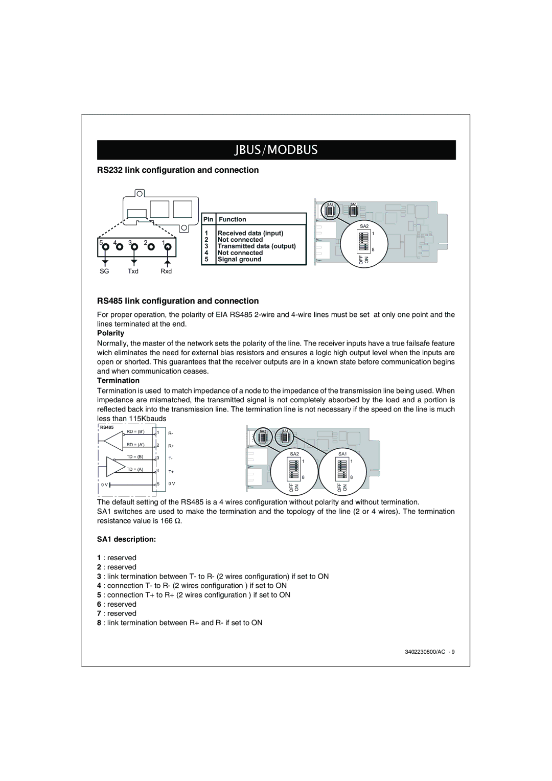
The UPS features multiple outlets for connecting several devices simultaneously, along with USB and serial connectivity options for integrating with other management systems. This flexibility is ideal for IT environments where multiple servers and network devices need protection. The APC 66123 also supports various communication protocols, allowing it to integrate seamlessly with existing power infrastructure.
Another important characteristic of the APC 66123 is its compact and space-saving design. Its efficient footprint ensures that it can be easily integrated into any workspace without sacrificing valuable real estate. Additionally, the unit operates quietly, making it suitable for use in office environments where noise levels must be kept to a minimum.
In terms of safety, the APC 66123 is certified by various international standards, ensuring compliance with stringent safety regulations. This certification guarantees that the unit not only performs effectively but also operates safely, providing peace of mind to users.
In conclusion, the APC 66123 is an exceptional choice for those seeking a reliable and efficient UPS system. With its advanced technology, user-friendly features, and commitment to safety, it serves as a critical solution for maintaining power continuity in diverse settings. Whether for personal use or as part of a larger power management strategy, the APC 66123 stands out as a trusted choice for safeguarding essential electronic systems.

