User Manual
Safety
This unit is intended for indoor use only. Do not operate this unit in direct sunlight, in contact with fluids, or where there is excessive dust or humidity.
Connect the
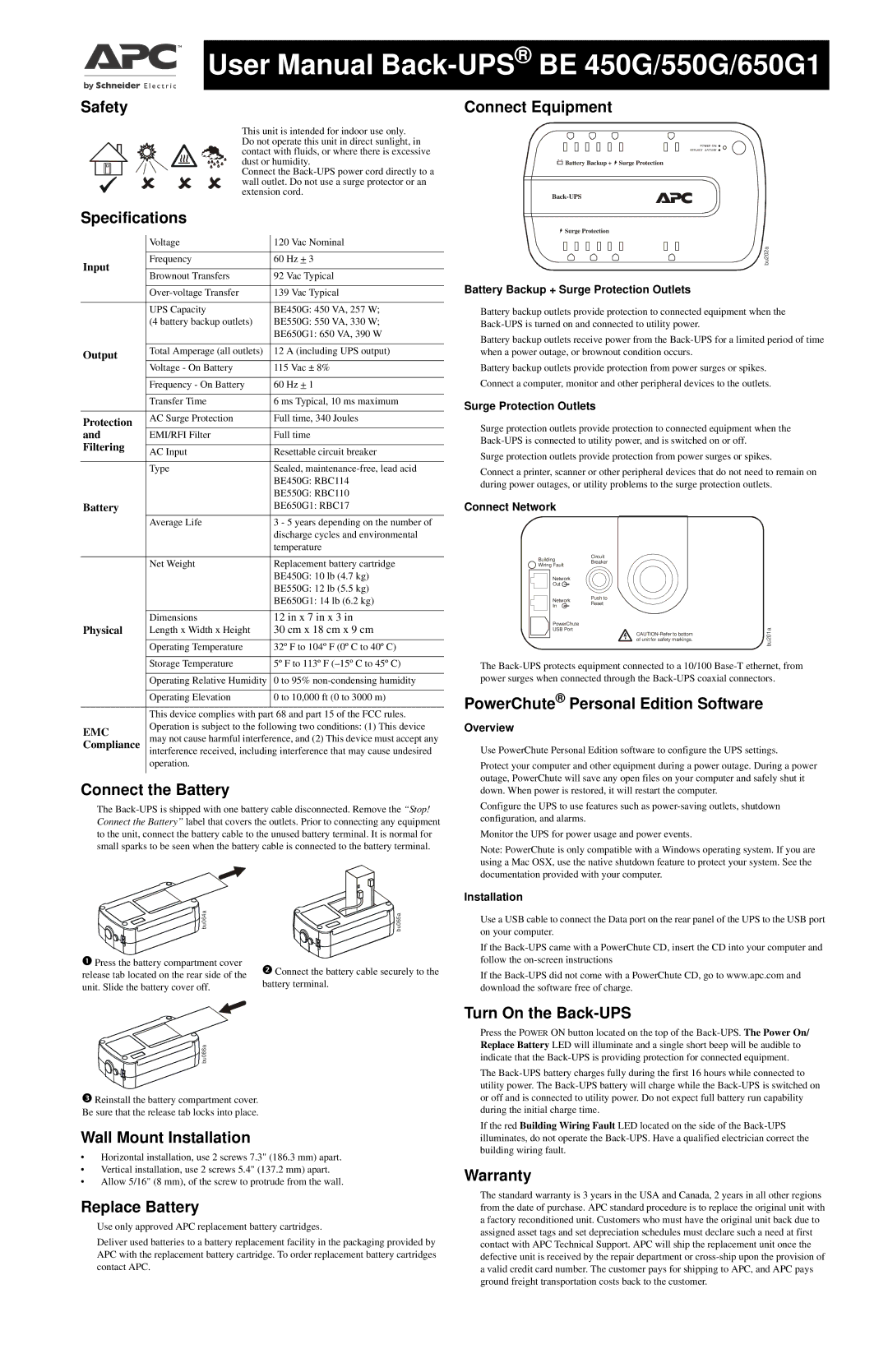
Connect Equipment
![]() Battery Backup +
Battery Backup + ![]() Surge Protection
Surge Protection
Specifications
| Voltage | 120 Vac Nominal | |
Input | Frequency | 60 Hz + 3 | |
|
| ||
Brownout Transfers | 92 Vac Typical | ||
| |||
|
|
| |
| 139 Vac Typical | ||
|
|
| |
| UPS Capacity | BE450G: 450 VA, 257 W; | |
| (4 battery backup outlets) | BE550G: 550 VA, 330 W; | |
|
| BE650G1: 650 VA, 390 W | |
|
|
| |
Output | Total Amperage (all outlets) | 12 A (including UPS output) | |
|
| ||
| Voltage - On Battery | 115 Vac ± 8% | |
|
|
| |
| Frequency - On Battery | 60 Hz + 1 | |
|
|
| |
| Transfer Time | 6 ms Typical, 10 ms maximum | |
|
|
| |
Protection | AC Surge Protection | Full time, 340 Joules | |
|
| ||
and | EMI/RFI Filter | Full time | |
Filtering |
|
| |
AC Input | Resettable circuit breaker | ||
| |||
|
|
| |
| Type | Sealed, | |
|
| BE450G: RBC114 | |
|
| BE550G: RBC110 | |
Battery |
| BE650G1: RBC17 | |
| Average Life | 3 - 5 years depending on the number of | |
|
| discharge cycles and environmental | |
|
| temperature | |
|
|
| |
| Net Weight | Replacement battery cartridge | |
|
| BE450G: 10 lb (4.7 kg) | |
|
| BE550G: 12 lb (5.5 kg) | |
|
| BE650G1: 14 lb (6.2 kg) | |
|
|
| |
| Dimensions | 12 in x 7 in x 3 in | |
Physical | Length x Width x Height | 30 cm x 18 cm x 9 cm | |
|
|
| |
| Operating Temperature | 32º F to 104º F (0º C to 40º C) | |
|
|
| |
| Storage Temperature | 5º F to 113º F | |
|
|
| |
| Operating Relative Humidity | 0 to 95% | |
|
|
| |
| Operating Elevation | 0 to 10,000 ft (0 to 3000 m) | |
|
|
| |
| This device complies with part | 68 and part 15 of the FCC rules. | |
EMC | Operation is subject to the following two conditions: (1) This device | ||
may not cause harmful interference, and (2) This device must accept any | |||
Compliance | |||
| interference received, including interference that may cause undesired | ||
| operation. |
| |
|
|
| |
Connect the Battery
The
bu064a | bu065a |
Press the battery compartment cover | Connect the battery cable securely to the |
release tab located on the rear side of the | |
unit. Slide the battery cover off. | battery terminal. |
|
![]()
![]()
![]()
![]()
![]()
![]()
![]()
![]() bu066a
bu066a
Reinstall the battery compartment cover. Be sure that the release tab locks into place.
Wall Mount Installation
•Horizontal installation, use 2 screws 7.3" (186.3 mm) apart.
•Vertical installation, use 2 screws 5.4" (137.2 mm) apart.
•Allow 5/16" (8 mm), of the screw to protrude from the wall.
Replace Battery
Use only approved APC replacement battery cartridges.
Deliver used batteries to a battery replacement facility in the packaging provided by APC with the replacement battery cartridge. To order replacement battery cartridges contact APC.
![]() Surge Protection
Surge Protection
bu202a
Battery Backup + Surge Protection Outlets
Battery backup outlets provide protection to connected equipment when the
Battery backup outlets receive power from the
Battery backup outlets provide protection from power surges or spikes. Connect a computer, monitor and other peripheral devices to the outlets.
Surge Protection Outlets
Surge protection outlets provide protection to connected equipment when the
Surge protection outlets provide protection from power surges or spikes.
Connect a printer, scanner or other peripheral devices that do not need to remain on during power outages, or utility problems to the surge protection outlets.
Connect Network
Building | Circuit |
|
Breaker |
| |
Wiring Fault |
| |
|
| |
Network |
|
|
Out |
|
|
Network | Push to |
|
Reset |
| |
In |
| |
|
| |
PowerChute |
| bu201a |
USB Port | ||
| ||
| of unit for safety markings. |
|
The
PowerChute® Personal Edition Software
Overview
Use PowerChute Personal Edition software to configure the UPS settings.
Protect your computer and other equipment during a power outage. During a power outage, PowerChute will save any open files on your computer and safely shut it down. When power is restored, it will restart the computer.
Configure the UPS to use features such as
Monitor the UPS for power usage and power events.
Note: PowerChute is only compatible with a Windows operating system. If you are using a Mac OSX, use the native shutdown feature to protect your system. See the documentation provided with your computer.
Installation
Use a USB cable to connect the Data port on the rear panel of the UPS to the USB port on your computer.
If the
If the
Turn On the Back-UPS
Press the POWER ON button located on the top of the
The
If the red Building Wiring Fault LED located on the side of the
Warranty
The standard warranty is 3 years in the USA and Canada, 2 years in all other regions from the date of purchase. APC standard procedure is to replace the original unit with a factory reconditioned unit. Customers who must have the original unit back due to assigned asset tags and set depreciation schedules must declare such a need at first contact with APC Technical Support. APC will ship the replacement unit once the defective unit is received by the repair department or