Chapter 2 Installation
Only trained service personnel should install and maintain the power supply enclosure.
Prior to installing the power supply enclosure, a utility breaker box must be installed on the pole. Utility line voltage must be routed to the enclosure. Local, state, federal and/or National Electric Code (NEC) regulations regarding location, permits and electrical wiring must be adhered to.
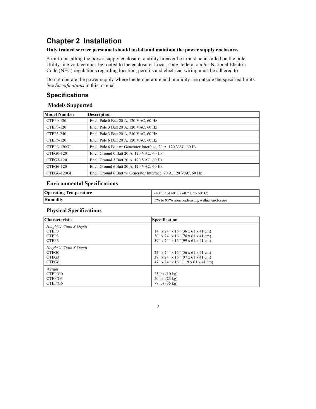
Do not operate the power supply where the temperature and humidity are outside the specified limits. See Specifications in this manual.
Specifications
Models Supported
Model Number | Description |
Encl, Pole 0 Batt 20 A, 120 VAC, 60 Hz | |
|
|
Encl, Pole 3 Batt 20 A, 120 VAC, 60 Hz | |
|
|
Encl, Pole 3 Batt 20 A, 240 VAC, 60 Hz | |
|
|
Encl, Pole 6 Batt 20 A, 120 VAC, 60 Hz | |
|
|
| Encl, Pole 6 Batt w/ Generator Interface, 20 A, 120 VAC, 60 Hz |
|
|
Encl, Ground 0 Batt 20 A, 120 VAC, 60 Hz | |
|
|
Encl, Ground 3 Batt 20 A, 120 VAC, 60 Hz | |
|
|
Encl, Ground 6 Batt 20 A, 120 VAC, 60 Hz | |
|
|
Encl, Ground 6 Batt w/ Generator Interface, 20 A, 120 VAC, 60 Hz | |
|
|
Environmental Specifications
Operating Temperature | |
Humidity | 5% to 95% noncondensing within enclosure |
|
|
Physical Specifications
Characteristic | Specification |
Height X Width X Depth |
|
CTEP0 | 14” x 24” x 16” (36 x 61 x 41 cm) |
CTEP3 | 30” x 24” x 16” (76 x 61 x 41 cm) |
CTEP6 | 39” x 24” x 16” (99 x 61 x 41 cm) |
Height X Width X Depth |
|
CTEG0 | 22” x 24” x 16” (56 x 61 x 41 cm) |
CTEG3 | 38” x 24” x 16” (97 x 61 x 41 cm) |
CTEG6 | 47” x 24” x 16” (119 x 61 x 41 cm) |
Weight |
|
CTEP/G0 | 23 lbs (10 kg) |
CTEP/G3 | 50 lbs (23 kg) |
CTEP/G6 | 77 lbs (35 kg) |
2
