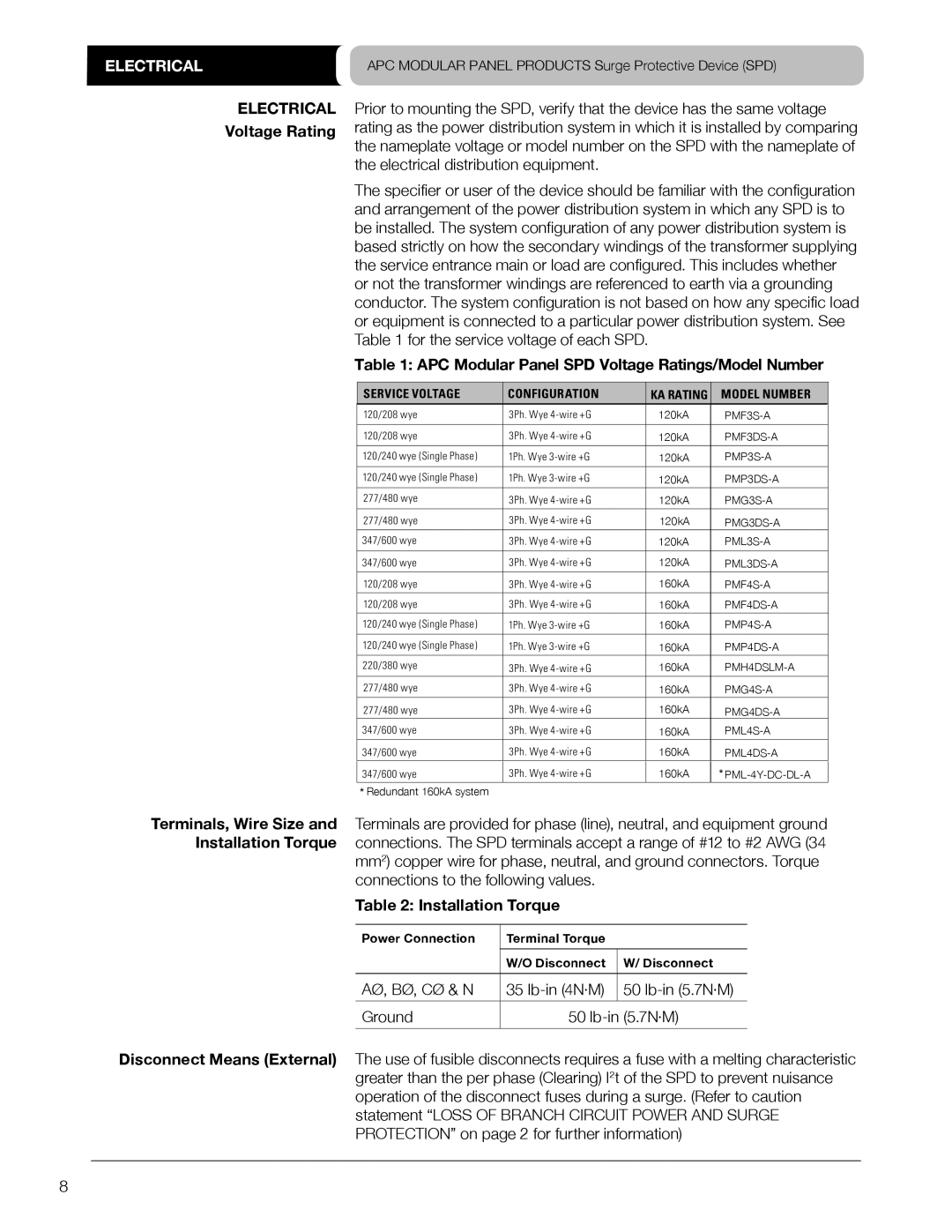
PMP3DS-A, PMG3DS-A, PML3S-A, PMG4DS-A, PMF4S-A specifications
The APC PML3DS-A, PMP3S-A, PMP4S-A, PMG4S-A, and PMP4DS-A are part of a product line designed for power management and distribution in various applications, from data centers to industrial setups. Each model boasts unique features and technologies that cater to specific operational needs while prioritizing efficiency, reliability, and safety.The APC PML3DS-A is a highly efficient power management solution suitable for small- to medium-sized enterprises. It features intelligent monitoring capabilities, allowing users to track power usage and optimize efficiency. The model integrates advanced surge protection technology, safeguarding equipment from voltage spikes. With a compact design, it offers flexibility in placement while still providing robust operational support.
The PMP3S-A model focuses on scalability, making it an excellent choice for businesses anticipating growth. This power management unit is compatible with multiple configurations, allowing seamless integration into existing systems. One of its standout features is the energy metering functionality, enabling precise tracking of energy consumption. This feature is invaluable for organizations seeking to reduce costs and improve sustainability initiatives.
Next in the lineup, the PMP4S-A offers enhanced power distribution capabilities, designed to handle higher loads. This unit is equipped with modular design elements, allowing for customization based on specific requirements. Additionally, it features real-time load balancing technology that ensures even distribution of power across connected devices, reducing the risk of overload and enhancing system stability.
The PMG4S-A stands out for its advanced management interface, providing users with a user-friendly experience. Its web-based management system allows remote monitoring and control, facilitating rapid response to any issues that arise. The PMG4S-A also includes built-in redundancy features, ensuring uninterrupted power supply and enhancing overall system resilience.
Lastly, the PMP4DS-A is engineered with advanced diagnostic capabilities, identifying potential issues before they can impact performance. This proactive approach to power management is crucial for maintaining operational integrity in critical systems. It also provides advanced communication options, integrating seamlessly with existing network infrastructure for improved management and reporting.
Together, these models from APC represent a comprehensive solution for power management, balancing performance, scalability, and safety across various applications. Their advanced features and technologies make them essential components for businesses looking to enhance their operational efficiency and reliability in power distribution.

