®
www.apc.com
Back-UPS™
RS 500
User’s Manual
Installation
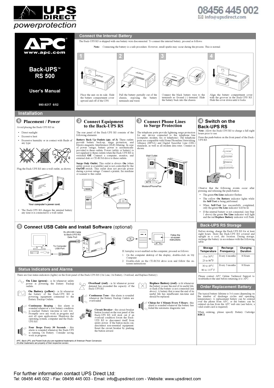
Connect the Internal Battery
The
Note: Connecting the battery is a safe procedure. However, small sparks may occur during the process. This is normal.
1 | 2 | 3 | 4 |
Place the unit on its side. Slide | Pull the battery partially out of the | Connect the black battery wire to the | Align the battery compartment cover |
the battery compartment cover | chassis, exposing the battery | terminals as Ground | with the grooves in the |
upward and off of the UPS. | terminals and wires. | the battery back into the chassis. | Slide the cover down until it locks. |
1Placement / Power
Avoid placing the
•Direct sunlight
•Excessive heat
•Excessive humidity or in contact with fluids of any type
Plug the
Your computer’s power cord.
•The
2Connect Equipment to the Back-UPS RS
The rear panel of the
Battery Back Up Outlets (qty. of 3). These outlets provide battery
Surge Only Outlet. This outlet is always On (when utility power is available) and is not controlled by the On/Off switch. This outlet does not provide power during a power outage. Connect a printer, fax machine or scanner to this outlet.
3Connect Phone Lines to Surge Protection
The telephone ports provide lightning surge protection for any device connected to the telephone line (computer, modem, fax or telephone). The telephone ports are compatible with Home Phoneline Networking Alliance (HPNA) and Digital Suscriber Line (DSL) standards, as well as all modem data rates. Connect as shown.
Wall Outlet
Modem/Phone/Fax
4Switch on the Back-UPS RS
Note: Allow the
Press the
UPS RS.
![]()
![]()
![]() ONLINE
ONLINE
![]()
![]()
![]()
![]()
![]()
![]() ON BATTERY
ON BATTERY
![]() OVERLOAD
OVERLOAD
![]()
![]()
![]()
![]()
![]() REPLACEBATTERY
REPLACEBATTERY
Observe that the following events occur after pressing and releasing the
•The green
•The yellow On Battery indicator lights while the
•When
•If the internal battery is not connected, (see Step 1 above) the green On Line indicator will light and the red Replace Battery indicator will flash.
5Connect USB Cable and Install Software (optional)
| |
to | Follow the |
Data Port | |
| instructions. |
To Computer
USB Port
If Autoplay is not enabled on the computer, proceed as follows:
1. On the computer desktop of the display,
2.
Status Indicators and Alarms
There are four status indicators (lights) on the front panel of the
Back-UPS RS Storage
Before storing, charge the
Storage | Recharge | Charging |
Temperature | Frenquency | Duration |
|
|
|
Every 6 months | 8 Hours | |
23 to 86oF |
|
|
30 to 45oC | Every 3 months | 8 Hours |
86 to 113o F |
|
|
Please contact APC Online Technical Support to troubleshoot the unit before returning it to APC.
On Line (green) - is lit whenever utility power is powering the Battery Backup outlets.
On Battery (yellow) - is lit whenever the battery of the
Continuous Beeping - this alarm is sounded whenever a low battery condition is reached. Battery
UPS RS.
Four Beeps Every 30 Seconds - this alarm is sounded whenever the
Overload (red) - is lit whenever power demand has exceeded the capacity of the
Continuous Tone - this alarm is sounded whenever the Battery Backup Outlets are overloaded.
Circuit Breaker - the circuit breaker button located on the rear panel of the
Replace Battery (red) - is lit whenever
the battery is near the end of its useful life, or flash if the battery is not connected (see above). A battery that is near the end of its useful life has insufficient
![]()
![]() Chirps for 1 Minute Every 5 Hours - this alarm is sounded whenever the battery has
Chirps for 1 Minute Every 5 Hours - this alarm is sounded whenever the battery has ![]() failed the automatic diagnostic test.
failed the automatic diagnostic test.
Order Replacement Battery
The typical battery lifetime is
When ordering, please specify Battery Cartridge RBC2.
APC,
For further information contact UPS Direct Ltd:
Tel: 08456 445 002 - Fax: 08456 445 003 - Email: info@upsdirect.com - Website: www.upsdirect.com