C H A P T E R 2
Hardware Modifications
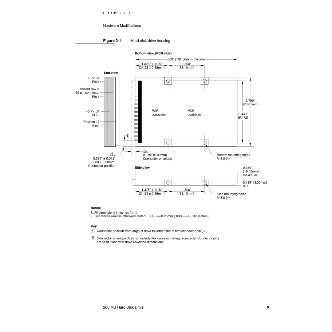
Figure 2-1 Hard disk drive housing
Bottom view (PCB side)
![]() 4.000" (101.60mm) maximum
4.000" (101.60mm) maximum ![]()
End view
8 Pin J2
Pin 1
Vacant row in
50 pin connector Pin 1
40 Pin J1
SCSI
Position 17 (key)
1.375" ± .015" | 1.500" |
(34.93 ± 0.38mm) | (38.10mm) |
PCBPCB
connectorcontroller
2.759"
(70.01mm)
2.430"
(61.72)
C
L
1 | 2 | Bottom mounting holes | ||||
| 0.079" (2.00mm) | |||||
0.387" ± 0.012" |
| Connector envelope | M 3.0 (4x) | |||
(9.83 ± 0.30mm) |
|
|
|
|
|
|
Connector position | Side view | 0.750" | ||||
| ||||||
|
|
|
|
|
| (19.05mm) |
|
|
|
|
|
| |
|
|
|
|
|
| maximum |
0.118" (3.00mm) 0.00
1.375" ± .015" | 1.500" |
| |
(34.93 ± 0.38mm) |
| (38.10mm) | Side mounting holes |
|
|
| M 3.0 (4x) |
Notes:
1.All dimensions in inches (mm).
2.Tolerances (unless otherwise noted): .XX =
Key:
1Connector position from edge of drive to center line of first connector pin (39).
2Connector envelope does not include flex cable or mating receptacle. Connector pins are to be flush with drive envelope dimensions.
200 MB Hard Disk Drive | 9 |