C H A P T E R 2
Hardware Modifications
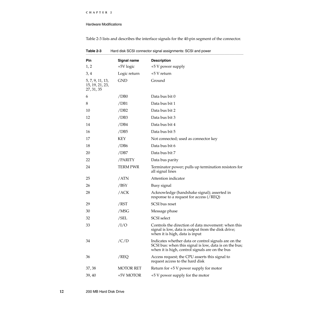
Table
Table
Pin | Signal name | Description |
1, 2 | +5V logic | +5 V power supply |
3, 4 | Logic return | +5 V return |
5, 7, 9, 11, 13, | GND | Ground |
15, 19, 21, 23, |
|
|
27, 31, 35 |
|
|
6 | /DB0 | Data bus bit 0 |
8 | /DB1 | Data bus bit 1 |
10 | /DB2 | Data bus bit 2 |
12 | /DB3 | Data bus bit 3 |
14 | /DB4 | Data bus bit 4 |
16 | /DB5 | Data bus bit 5 |
17 | KEY | Not connected; used as connector key |
18 | /DB6 | Data bus bit 6 |
20 | /DB7 | Data bus bit 7 |
22 | /PARITY | Data bus parity |
24 | TERM PWR | Terminator power; pulls up termination resistors for |
|
| all signal lines |
25 | /ATN | Attention indicator |
26 | /BSY | Busy signal |
28 | /ACK | Acknowledge (handshake signal); asserted in |
|
| response to a request for access (/REQ) |
29 | /RST | SCSI bus reset |
30 | /MSG | Message phase |
32 | /SEL | SCSI select |
33 | /I/O | Controls the direction of data movement: when this |
|
| signal is low, data is output from the disk drive; |
|
| when it is high, data is input |
34 | /C/D | Indicates whether data or control signals are on the |
|
| SCSI bus: when this signal is low, data is on the bus; |
|
| when it is high, control signals are on the bus |
36 | /REQ | Access request; the CPU asserts this signal to |
|
| request access to the hard disk |
37, 38 | MOTOR RET | Return for +5 V power supply for motor |
39, 40 | +5V MOTOR | +5 V power supply for the motor |
12 | 200 MB Hard Disk Drive |