C H A P T E R 2
Hardware Modifications
Table
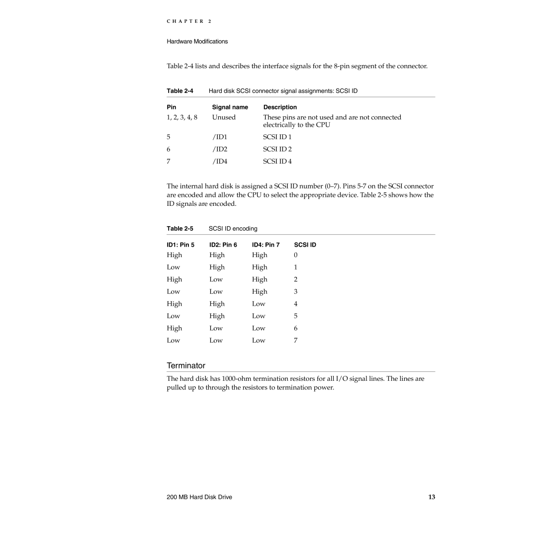
Table | Hard disk SCSI connector signal assignments: SCSI ID | |
|
|
|
Pin | Signal name | Description |
1, 2, 3, 4, 8 | Unused | These pins are not used and are not connected |
|
| electrically to the CPU |
5 | /ID1 | SCSI ID 1 |
6 | /ID2 | SCSI ID 2 |
7 | /ID4 | SCSI ID 4 |
The internal hard disk is assigned a SCSI ID number
Table | SCSI ID encoding |
| |
|
|
|
|
ID1: Pin 5 | ID2: Pin 6 | ID4: Pin 7 | SCSI ID |
High | High | High | 0 |
Low | High | High | 1 |
High | Low | High | 2 |
Low | Low | High | 3 |
High | High | Low | 4 |
Low | High | Low | 5 |
High | Low | Low | 6 |
Low | Low | Low | 7 |
Terminator
The hard disk has
200 MB Hard Disk Drive | 13 |
