3-3-15. MIC Level/MIC Level IND Adjustment
Equipment: Oscilloscope
Preparation: OUTPUT/DL/DCC+ switch: BARS
Adjustment Procedure
MIC Level Adjustment
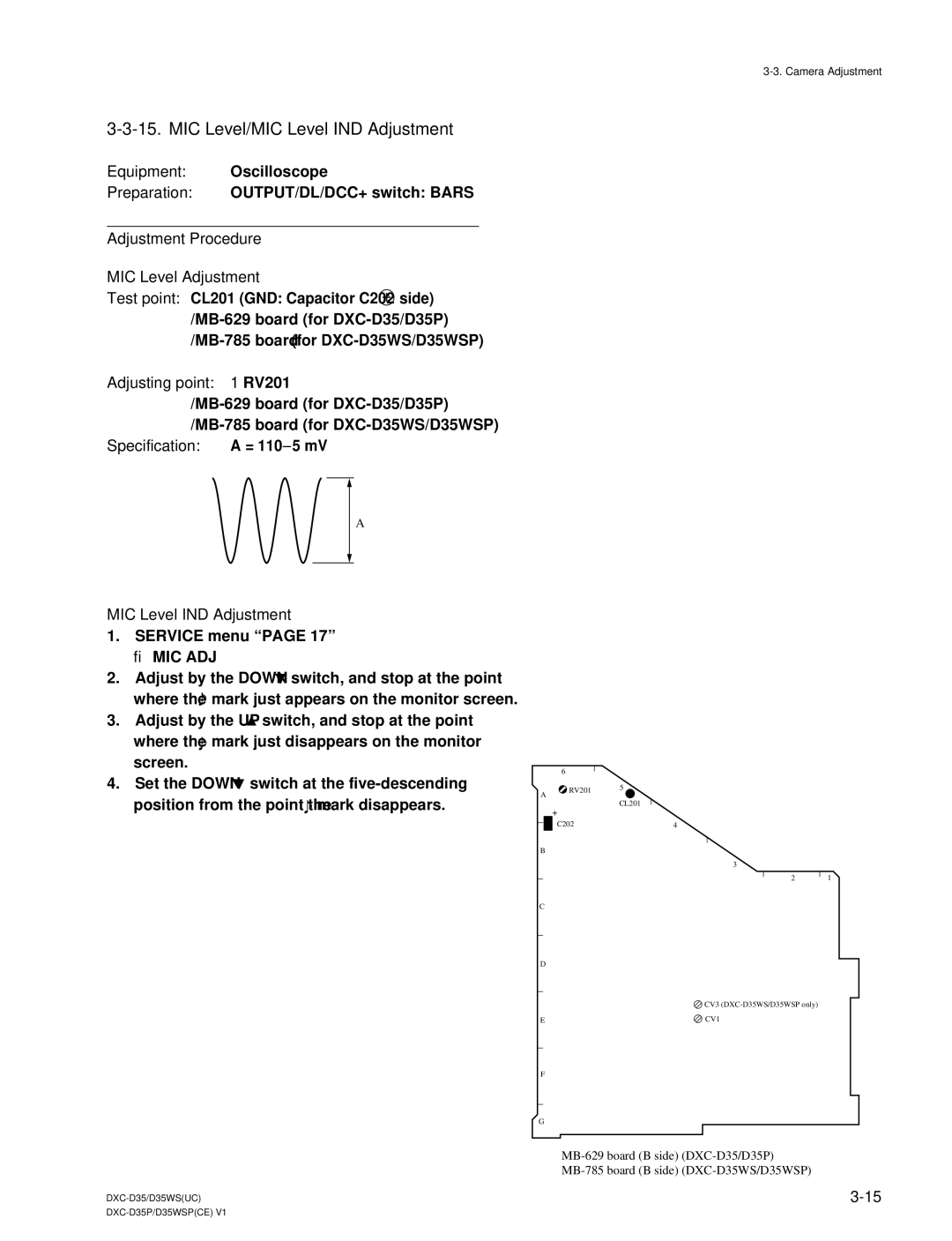
Test point: CL201 (GND: Capacitor C202 +
Adjusting point: 1RV201
Specification: A = 110 ±5 mV
A
MIC Level IND Adjustment
1.SERVICE menu “PAGE 17”
→ MIC ADJ
2.Adjust by the DOWN ![]() switch, and stop at the point where the
switch, and stop at the point where the ![]() mark just appears on the monitor screen.
mark just appears on the monitor screen.
3.Adjust by the UP ![]() switch, and stop at the point where the
switch, and stop at the point where the ![]() mark just disappears on the monitor screen.
mark just disappears on the monitor screen.
4.Set the DOWN ![]() switch at the
switch at the ![]() mark disappears.
mark disappears.
| 6 |
|
A | RV201 | 5 |
| ||
|
| |
|
| CL201 |
| + |
|
| C202 | 4 |
B
3
2 1
C
D
CV3
E | CV1 |
F
G