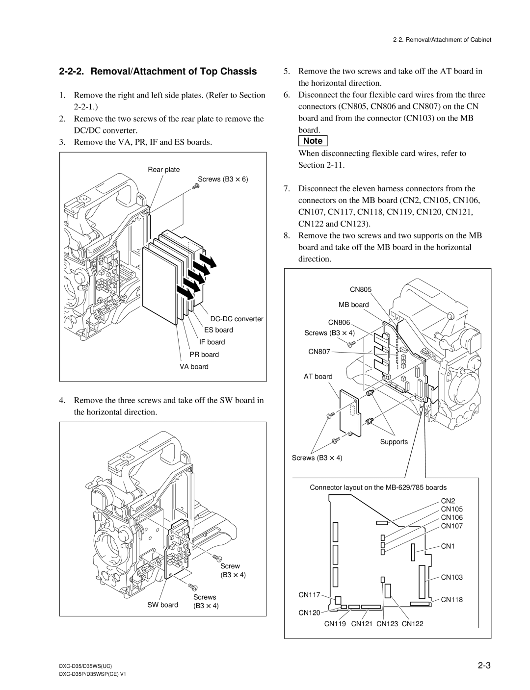
2-2-2. Removal/Attachment of Top Chassis
1.Remove the right and left side plates. (Refer to Section
2.Remove the two screws of the rear plate to remove the DC/DC converter.
3.Remove the VA, PR, IF and ES boards.
Rear plate |
Screws (B3 x6) |
ES board |
IF board |
PR board |
VA board |
4.Remove the three screws and take off the SW board in the horizontal direction.
Screw (B3 x4)
Screws
SW board (B3 x4)
5.Remove the two screws and take off the AT board in the horizontal direction.
6.Disconnect the four flexible card wires from the three connectors (CN805, CN806 and CN807) on the CN board and from the connector (CN103) on the MB board.
n
When disconnecting flexible card wires, refer to Section
7.Disconnect the eleven harness connectors from the connectors on the MB board (CN2, CN105, CN106, CN107, CN117, CN118, CN119, CN120, CN121, CN122 and CN123).
8.Remove the two screws and two supports on the MB board and take off the MB board in the horizontal direction.
| CN805 |
MB board | |
CN806 | |
Screws (B3 x4) | |
CN807 |
|
AT board |
|
| Supports |
Screws (B3 x4) |
|
Connector layout on the | |
| CN2 |
| CN105 |
| CN106 |
| CN107 |
| CN1 |
| CN103 |
CN117 | CN118 |
| |
CN120 |
|
CN119 | CN121 CN123 CN122 |
| |
