3-3-7. Y (VBS) Level Adjustment
Equipment: | Waveform monitor |
To be extended: | |
| |
Preparation: | OUTPUT/DL/DCC+ switch: BARS |
Test point: | VIDEO OUT connector |
Adjustment Procedure
1.[for NTSC]
. SERVICE menu “PAGE 9”
→SET UP : ON
[for PAL]
.SERVICE menu “PAGE 9” →COMP LVL: 525 (not 700)
2.Adjusting point: 1RV501 (Y LEVEL)
B = 700 ± 10 mV (for PAL)
[for NTSC] | [for PAL] |
3-3-8. Y (YC) Level Adjustment
n
Be sure that
Equipment: | Oscilloscope |
To be extended: | |
| |
Preparation: | OUTPUT/DL/DCC +switch: BARS |
Test point: | TP66 (GND: |
Trigger: | HD |
Adjusting point: 1RV502 (Y LEVEL)
Specification: A = 1.00 ± 0.02 V (for NTSC) A = 1.00 ± 0.02 V (for PAL)
[for NTSC] | [for PAL] |
n
In the NTSC model, check that the set up level is within A = 7.5 ± 5.0 IRE.
If without the range, perform the setup level adjustment in Section
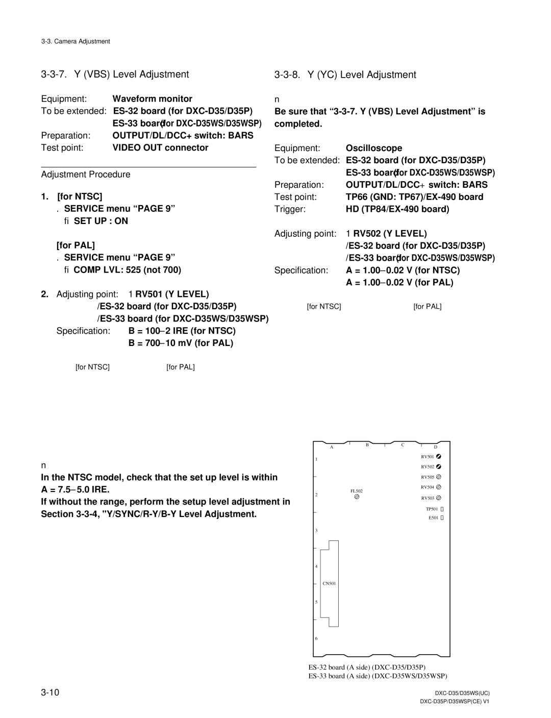
1
2
3
4
5
6
AB
FL502
CN501
CD
RV501 ![]() RV502
RV502 ![]() RV505
RV505 ![]() RV504
RV504 ![]() RV503
RV503 ![]()
TP501 ![]()
![]()
E501 ![]()
![]()