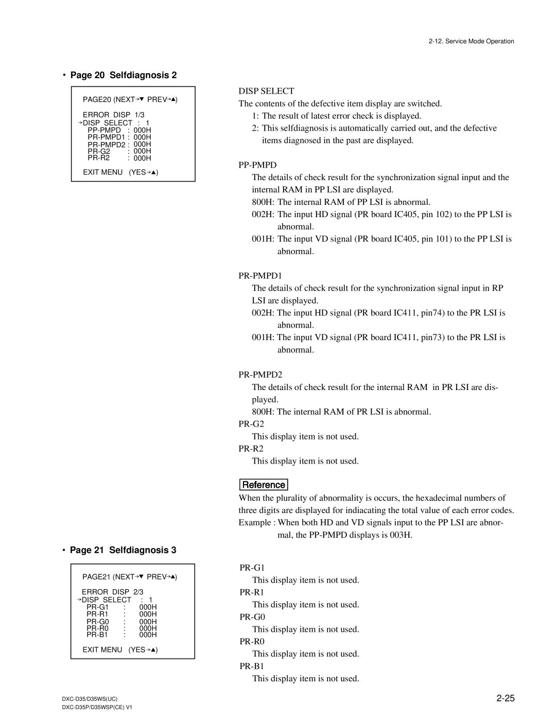
.Page 20 Selfdiagnosis 2
PAGE20 (NEXT![]() PREV
PREV![]() )
)
ERROR DISP 1/3
![]() DISP SELECT : 1
DISP SELECT : 1
: 000H | |
: 000H | |
: 000H | |
EXIT MENU | (YES ) |
.Page 21 Selfdiagnosis 3
PAGE21 (NEXT![]() PREV
PREV![]() )
)
ERROR DISP 2/3
![]() DISP SELECT : 1
DISP SELECT : 1
EXIT MENU (YES![]() )
)
DISP SELECT
The contents of the defective item display are switched.
1:The result of latest error check is displayed.
2:This selfdiagnosis is automatically carried out, and the defective items diagnosed in the past are displayed.
PP-PMPD
The details of check result for the synchronization signal input and the internal RAM in PP LSI are displayed.
800H: The internal RAM of PP LSI is abnormal.
002H: The input HD signal (PR board IC405, pin 102) to the PP LSI is abnormal.
001H: The input VD signal (PR board IC405, pin 101) to the PP LSI is abnormal.
PR-PMPD1
The details of check result for the synchronization signal input in RP LSI are displayed.
002H: The input HD signal (PR board IC411, pin74) to the PR LSI is abnormal.
001H: The input VD signal (PR board IC411, pin73) to the PR LSI is abnormal.
PR-PMPD2
The details of check result for the internal RAM in PR LSI are dis- played.
800H: The internal RAM of PR LSI is abnormal.
This display item is not used.
This display item is not used.
[Reference]
When the plurality of abnormality is occurs, the hexadecimal numbers of three digits are displayed for indiacating the total value of each error codes. Example : When both HD and VD signals input to the PP LSI are abnor-
mal, the
This display item is not used.
This display item is not used.
This display item is not used.
This display item is not used.
This display item is not used.
