3-3-12. Carrier Adjustment at DPR (Double Pixel Reading) ON
Equipment: Waveform monitor, Vectorscope (MAX GAIN)
Preparation:
.HYPER GAIN switch: ON
.OUTPUT/DL/DCC +switch: CAM/DCC +
Test point: VIDEO OUT connector
Adjustment Procedure
1.SEVICE menu “PAGE25”
→R D.DARK: G D.DARK: B D.DARK:
2.Set the lens iris to the close (C).
3.Adjust the settings of R D.DARK, G D.DARK and B D.DARK by UP ![]() switch or DOWN
switch or DOWN ![]() switch to meet the specifications 1 and 2 below.
switch to meet the specifications 1 and 2 below.
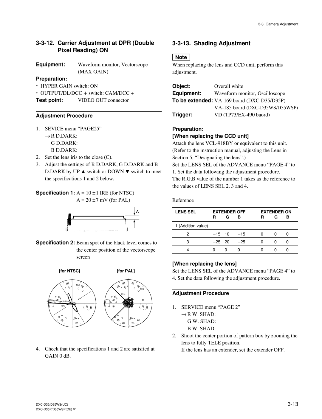
Specification 1: A = 10 ± 1 IRE (for NTSC) A = 20 ± 7 mV (for PAL)
Specification 2: Beam spot of the black level comes to the center position of the vectorscope screen
[for NTSC] |
| [for PAL] |
| |
| MG |
| R |
|
| R |
| MG | |
|
|
|
| |
YL |
| YL | 75% |
|
|
|
| ||
| 100% |
|
|
|
| 75% |
|
| B |
| B |
|
| |
G | CY | G | CY |
|
|
|
| ||
4.Check that the specifications 1 and 2 are satisfied at GAIN 0 dB.
3-3-13. Shading Adjustment
n
When replacing the lens and CCD unit, perform this adjustment.
Object: | Overall white |
Equipment: | Waveform monitor, Oscilloscope |
To be extended: | |
| |
Trigger: | VD |
Preparation:
[When replacing the CCD unit]
Attach the lens
Set the LENS SEL of the ADVANCE menu “PAGE 4” to 1. Set the data following the adjustment procedure.
The R,G,B value of the number 1 takes as the reference to the values of LENS SEL 2, 3 and 4.
Reference
LENS SEL | EXTENDER OFF | EXTENDER ON | ||||
| R | G | B | R | G | B |
|
|
|
|
|
|
|
1 (Addition value) |
|
|
|
|
|
|
|
|
|
|
|
|
|
2 | _15 | 10 | _15 | 0 | 0 | 0 |
|
|
|
|
|
|
|
3 | _25 | 20 | _25 | 0 | 0 | 0 |
|
|
|
|
|
|
|
4 | 0 | 0 | 0 | 0 | 0 | 0 |
|
|
|
|
|
|
|
[When replacing the lens]
Set the LENS SEL of the ADVANCE menu “PAGE 4” to 4. Set the data following the adjustment procedure.
Adjustment Procedure
1.SERVICE menu “PAGE 2”
→R W. SHAD: G W. SHAD: B W. SHAD:
2.Shoot the center portion of pattern box by zooming the lens to fully TELE position.
If the lens has an extender, set the extender OFF.