3-3-11. CCD Output Level Adjustment
m
.Usually, this adjustment is not required.
Only when the output level of CCD unit is largely different from the specification, make the adjustment.
.When the new CCD unit for spare parts is replaced, this adjustment is not required because of the correct adjust- ment at the factory.
.It is advisable to use a reflection type grayscale chart for this adjustment. Further more, before adjustment, setting of the luminance (or brightness) on the chart surface and the color temperature setting are required. For details, refer to Section
Lightening: | 3200K, 2000 lux |
| (When using the pattern box, set to |
| Auto mode.) |
Object: | Grayscale chart |
Equipment: | Oscilloscope |
To be extended:
Preparation:
.OUTPUT/DL/DCC+ switch: CAM/DCC +
.W. BAL switch: PRESET
.Select a large lens iris to shoot the gray scale chart covering fully the underscanned frame.
(Refer to Section
.Adjust the lens iris so that the video level at TP27/ extension board
Trigger: HD
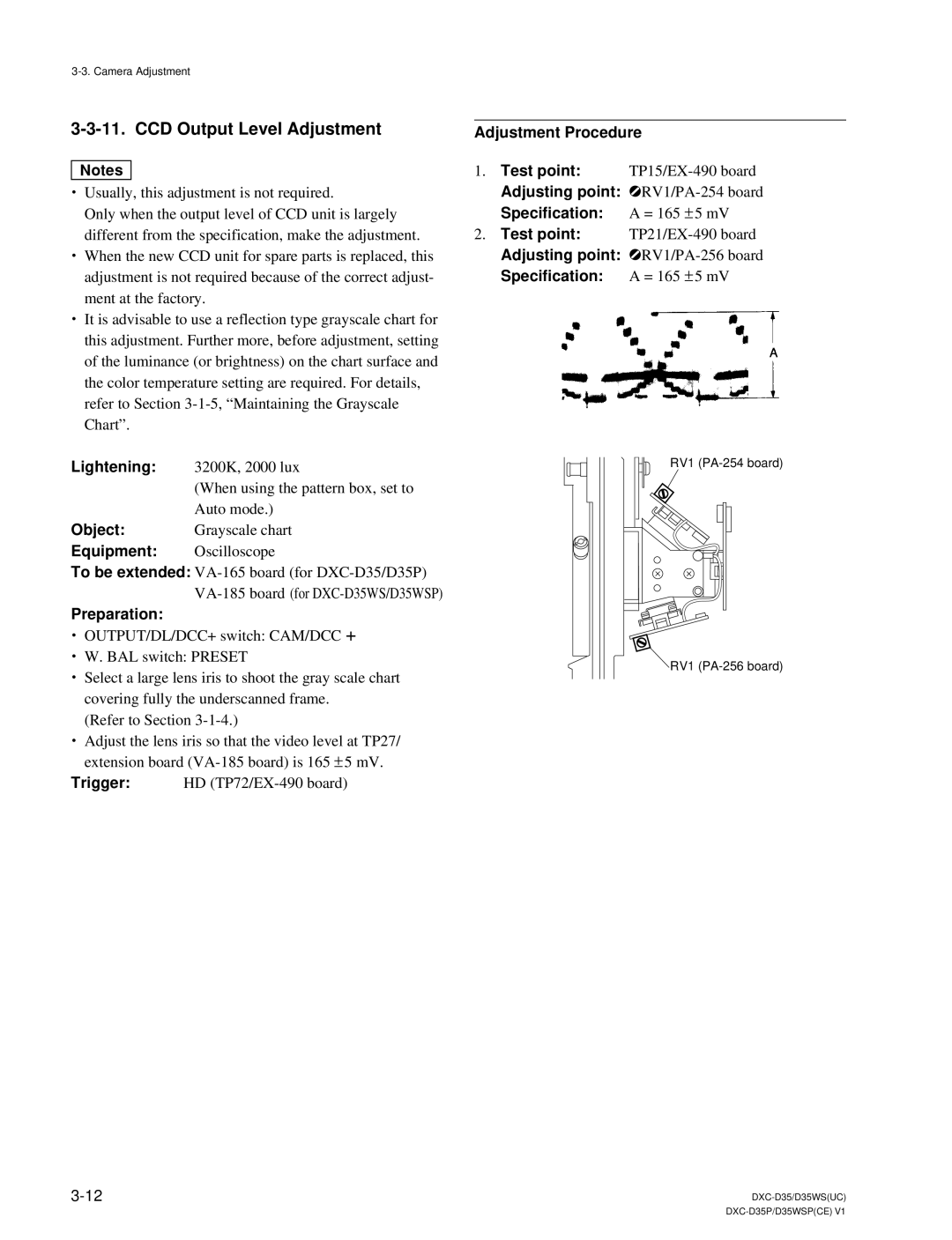
Adjustment Procedure
1. | Test point: | |
| Adjusting point: | |
| Specification: | A = 165 ± 5 mV |
2. | Test point: | |
| Adjusting point: | |
| Specification: | A = 165 ± 5 mV |
RV1
RV1
