Connections
VTR
VIDEO IN
![]()
![]()
Headset
Headset
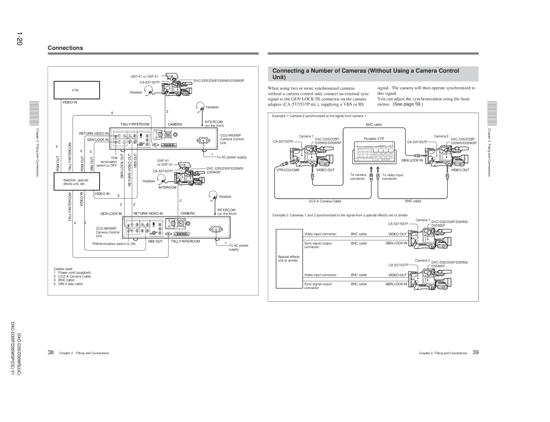
Connecting a Number of Cameras (Without Using a Camera Control Unit)
When using two or more synchronized cameras | signal. The camera will then operate synchronized to |
without a camera control unit, connect an external sync | this signal. |
signal to the GEN LOCK IN connector on the camera | You can adjust the synchronization using the basic |
adaptor | menus. (See page 59.) |
42
|
|
|
|
|
| TALLY/INTERCOM | CAMERA | INTERCOM | |||
|
|
|
|
|
| (on the front) | |||||
Chapter2 |
|
|
|
|
|
|
|
|
|
| |
|
|
| GEN LOCK IN |
|
|
|
|
| Camera Control | ||
|
|
| RETURN VIDEO IN |
|
|
|
|
| |||
|
|
|
|
|
|
|
|
|
|
| |
Fitting |
| TALLY/INTERCOM | OUTPGM |
|
|
|
|
|
|
| Unit |
3 |
|
|
|
|
|
|
| ||||
andConnections |
|
| 3 | 3 |
| LOCKGENOUT | VIDEORETURNOUT | VBSOUT |
|
| 1 |
OUTPGM |
|
|
|
|
|
| |||||
efects unit, etc. | OUTVBS | 75Ω | To AC power supply | ||||||||
termination |
| ||||||||||
|
|
|
|
|
|
|
|
| |||
|
|
|
|
|
|
|
| or |
| ||
|
|
|
|
| switch to OFF |
|
|
|
| ||
|
|
|
|
|
|
|
|
|
|
| |
|
|
|
|
|
|
|
|
| D35WSP | ||
|
|
|
|
|
|
|
|
|
|
| |
|
| Switcher, special |
|
|
|
| Headset |
|
| ||
|
|
|
|
|
|
|
|
|
|
| |
|
| TALLY/INTERCOM | INVIDEO |
|
|
|
|
| INTERCOM |
| |
|
|
| VIDEO IN | 3 |
|
|
|
| Headset | ||
|
|
|
|
|
|
|
|
|
| ||
|
|
|
|
|
|
|
|
|
| 2 |
|
|
|
|
|
|
| 3 |
| 3 |
|
|
|
|
|
|
|
| GEN LOCK IN |
| RETURN VIDEO IN | CAMERA | INTERCOM | ||
|
|
|
|
|
| (on the front) | |||||
|
| 4 |
| 3 |
|
|
|
|
|
|
|
|
|
|
|
|
|
|
|
|
|
| |
|
|
|
|
| Camera Control |
|
|
|
|
| |
|
|
|
|
| Unit |
|
|
|
|
|
|
|
|
|
| 75Ω termination switch to ON | VBS OUT | TALLY/INTERCOM | 1 | ||||
|
|
|
|
|
| ||||||
|
|
|
|
|
|
|
|
|
|
| To AC power |
supply
Cables used
1Power cord (supplied)
2
3 BNC cable
4 DIN
Example 1: Camera 2 synchronized to the signal from camera 1 |
|
| ||
|
| BNC cable |
|
|
Camera 1 | Portable VTR | Camera 2 | ||
D35WS/D35WSP |
| D35WS/D35WSP | ||
|
|
| ||
|
|
| GEN LOCK IN |
|
VTR/CCU/CMA | VIDEO OUT |
|
| VIDEO OUT |
|
| To camera | To video input |
|
|
| connector | connector |
|
|
| BNC cable |
| |
Example 2: Cameras 1 and 2 synchronized to the signal from a special effects unit or similar |
| |||
|
|
| Camera 1 | |
|
|
| D35WSP | |
| Video input connector | BNC cable | VIDEO OUT |
|
| Sync signal output | BNC cable | GEN LOCK IN |
|
| connector |
|
|
|
Special effects |
|
|
|
|
unit or similar |
|
| Camera 2 | |
|
|
| D35WSP | |
| Video input connector | BNC cable | VIDEO OUT |
|
| Sync signal output | BNC cable | GEN LOCK IN |
|
| connector |
|
|
|
Chapter 2 Fitting and Connections
38 | Chapter 2 Fitting and Connections |
Chapter 2 Fitting and Connections | 39 |
