2-4-2. Connection Connector
Connections made with the connector panels during installation or service, should be made with the connectors or complete cable assemblies specified in the following list, or equivalent parts.
Connector Name | Parts No. and name of connector | |
with cable | ||
| ||
|
| |
REMOTE | ||
| CONNECTOR, ROUND 10P, MALE | |
| HIROSE HR | |
(10P, FEMALE) | or | |
| (optional) | |
|
| |
VIDEO OUT | ||
(BNC) | PLUG, BNC | |
|
| |
MONITOR OUT | ||
(BNC) | PLUG, BNC | |
|
| |
VF | ||
(8P, FEMALE) | CABLE, VF | |
|
| |
LENS | ||
| CONNECTOR, 12P, MALE | |
(12P, FEMALE) | HIROSE HR | |
|
| |
MIC | ||
| CONNECTOR, 3P, MALE | |
(3P, FEMALE) | CANNON | |
|
| |
VF | ||
| CONNECTOR, 20P, MALE | |
(20P, FEMALE) | HIROSE HR | |
|
|
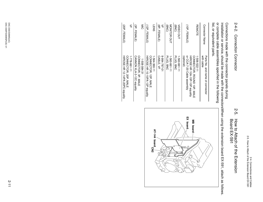
2-5. How to Attach of the Extension Board EX-591
When using the extension board EX-591, attach as follows.
MB board ![]()
EX board
CN2