Location and Function of Parts
Chapter 1 Overview
7REMOTE connector 1 (mini-jack)
Connect the
8MONITOR OUT connector (BNC) Outputs both the camera video and the character information as displayed on the viewfinder screen.
You can connect an optional LCD color monitor to this connector.
9VIDEO OUT connector (BNC)
This outputs the video signal captured by the camera.
0REMOTE connector 2 (10-pin)
Connect the optional
Note
When using the
•When operating the camera head from the camera control unit, connect the
•EZ mode cannot be used if the
qa LENS connector
Connect the lens connector.
qs VF (viewfinder) connector (8-pin)
This is the connector for the
Note
When using this connector, do not connect a
qd VTR connectors (PRO 76-pin DIGITAL and PRO 50-pin)
Connect a dockable VTR. A PRO
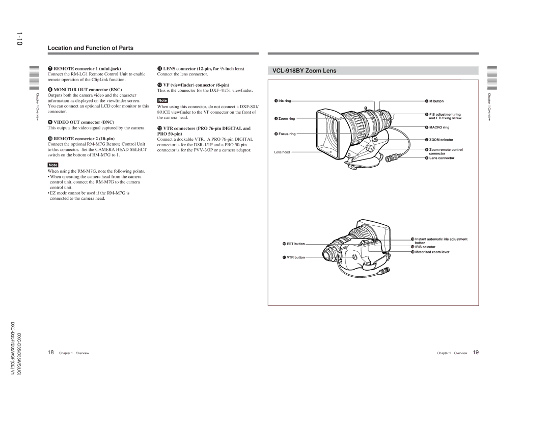
VCL-918BY Zoom Lens
1Iris ring
2 Zoom ring
3 Focus ring
Lens hood
0RET button
qa VTR button
4 M button | Chapter 1 |
and F.B fixing screw | Overview |
5 F.B adjustment ring |
|
6 MACRO ring |
|
7 ZOOM selector |
|
8Zoom remote control connector
9Lens connector
qs Instant automatic iris adjustment button
qd IRIS selector
qf Motorized zoom lever
DXC- |
| |
D35P/D35WSP(CE)V1 | Chapter 1 Overview | |
| 18 |
Chapter 1 Overview 19
