3-3-17. 4 : 3 Title Adjustment (Only for DXC- D35WS/D35WSP)
Equipment: Color monitor (or, B/W monitor)
Preparation: OUTPUT/DL/DCC +switch: BARS
Test point: MONITOR OUT connector
Adjustment Procedure
1.Select “PAGE 9” on the ADVANCE menu, set “16:9/4:3” to “4:3” position.
2.Select “PAGE 8” on the ADVANCE menu, set “CLOCK IND” to “BARS” position.
3.Set the cursor to “EXIT MENU” then press the UP ![]() switch to return to the menu selecting screen.
switch to return to the menu selecting screen.
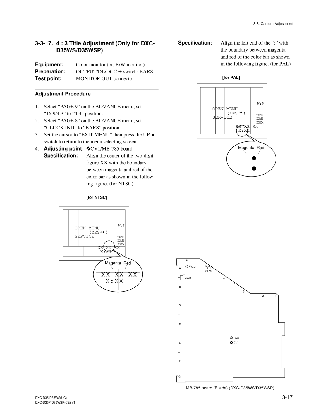
4.Adjusting point: 1CV1/MB-785 board
Specification: Align the center of the
figure XX with the boundary between magenta and red of the color bar as shown in the follow- ing figure. (for NTSC)
[for NTSC] | |
OPEN MENU | W:P |
| |
(YES | ) |
SERVICE | TONE |
| XXdB |
| XXXX |
XX XX XX | |
| X:XX |
| Magenta Red |
XX XX XX
X:XX
Specification: Align the left end of the “:” with the boundary between magenta and red of the color bar as shown in the following figure. (for PAL)
[for PAL] |
| |
|
| W:P |
OPEN MENU |
|
|
(YES | ) | TONE |
SERVICE |
| |
| XXdB | |
|
| XXXX |
XX XX XX | ||
| X:XX |
|
Magenta Red
| 6 |
|
A | RV201 | 5 |
| ||
|
|
CL201
+
C202 | 4 |
B
3
2 1
C
D
![]() CV3
CV3
E | CV1 |
F
G