V1 |
|
Connections
Connecting a Portable VTR
| Using the optional |
| Camera Adaptor and a camera cable, you can connect |
| a portable VTR. Set the VTR selector switch on the |
| camera adaptor according to the VTR connected. |
| If using a VTR from another manufacturer, consult your |
| |
| |
| |
| |
| |
| |
| |
| Sony dealer. |
| |
| |
| |
|
|
|
|
|
|
|
|
|
|
|
|
|
|
|
|
Chapter2 | Checks before making connections |
| |
Fitting | Check first that the video camera, camera adaptor, |
VTR, and other devices are all powered off. | |
and |
|
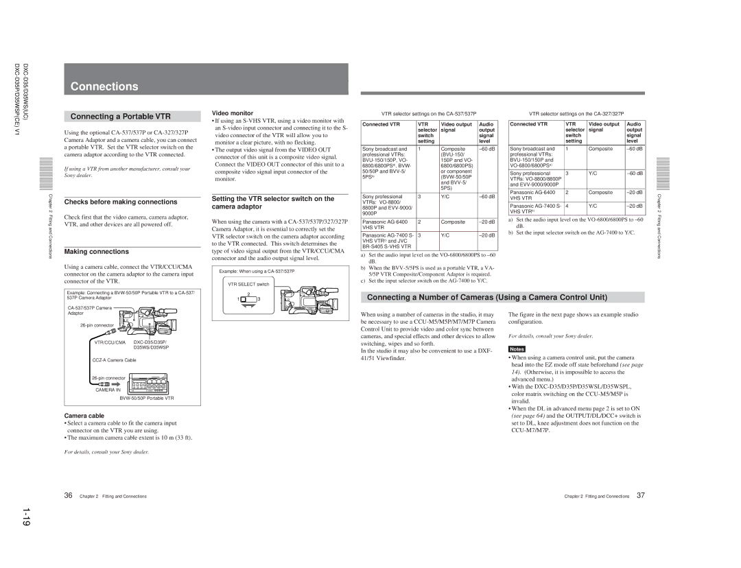
Connections | Making connections |
| |
| Using a camera cable, connect the VTR/CCU/CMA |
| connector on the camera adaptor to the camera input |
| connector of the VTR. |
| Example: Connecting a |
Video monitor
•If using an
•The output video signal from the VIDEO OUT connector of this unit is a composite video signal. Connect the VIDEO OUT connector of this unit to a composite video signal input connector of the monitor.
Setting the VTR selector switch on the camera adaptor
When using the camera with a
Example: When using a
VTR SELECT switch
VTR selector settings on the |
| ||
Connected VTR | VTR | Video output | Audio |
| selector | signal | output |
| switch |
| signal |
| setting |
| level |
Sony broadcast and | 1 | Composite | |
professional VTRs: |
|
| |
| 150P and VO- |
| |
6800/6800PSa), BVW- |
| 6800/6800PS) |
|
50/50P and |
| or component |
|
5PSb) |
|
| |
|
| and |
|
|
| 5PS) |
|
Sony professional | 3 | Y/C | |
VTRs: |
|
|
|
8800P and |
|
|
|
9000P |
|
|
|
Panasonic | 2 | Composite | |
VHS VTR |
|
|
|
Panasonic | 3 | Y/C | |
VHS VTRc) and JVC |
|
|
|
|
|
| |
a)Set the audio input level on the VO-6800/6800PS to –60 dB.
b)When the
c)Set the input selector switch on the AG-7400 to Y/C.
VTR selector settings on the |
| ||
Connected VTR | VTR | Video output | Audio |
| selector | signal | output |
| switch |
| signal |
| setting |
| level |
Sony broadcast and | 1 | Composite | |
professional VTRs: |
|
|
|
|
|
| |
|
|
| |
Sony professional | 3 | Y/C | |
VTRs: |
|
|
|
and |
|
|
|
Panasonic | 2 | Composite | |
VHS VTR |
|
|
|
Panasonic | 4 | Y/C | |
VHS VTRb) |
|
|
|
a)Set the audio input level on the
b)Set the input selector switch on the
Chapter 2 Fitting and Connections
537P Camera Adaptor |
2
1![]() 3
3
Connecting a Number of Cameras (Using a Camera Control Unit)
Adaptor |
VTR/CCU/CMA |
D35WS/D35WSP |
CAMERA IN |
Camera cable
•Select a camera cable to fit the camera input connector on the VTR you are using.
•The maximum camera cable extent is 10 m (33 ft).
For details, consult your Sony dealer.
When using a number of cameras in the studio, it may be necessary to use a
In the studio it may also be convenient to use a DXF- 41/51 Viewfinder.
The figure in the next page shows an example studio configuration.
For details, consult your Sony dealer.
Notes
•When using a camera control unit, put the camera head into the EZ mode off state beforehand (see page 14). (Otherwise, it is impossible to access the advanced menu.)
•With the
•When the DL in advanced menu page 2 is set to ON (see page 64) and the OUTPUT/DL/DCC+ switch is set to DL, knee adjustment does not function on the
36 | Chapter 2 Fitting and Connections |
Chapter 2 Fitting and Connections | 37 |