Chapter 1 Overview
Location and Function of Parts
1EZ (“easy”) MODE button and indicator Depress this button (EZ mode on) when you want to be able to shoot immediately, with automatic adjustment of the camera settings to standard values. (See page 68.) When this function is used, the iris and the white balance are adjusted automatically. (The total level control system functions.) Press this button again to return the camera to the previous settings (EZ mode off).
Note
When connecting the
2EZ FOCUS button
Press this button to turn the “easy focus” function on. This opens the iris, to make it easier to focus before beginning shooting. The indication “EZ FOCUS” appears in the viewfinder while the function is on; to turn it off, press the EZ FOCUS button again. If left on, the function automatically turns off after about ten seconds.
Note
If the “easy focus” function is still on when you press the VTR button, it turns off automatically and recording starts about one second later.
3EDIT SEARCH buttons (for operation with DSR-1/1P)
When using the
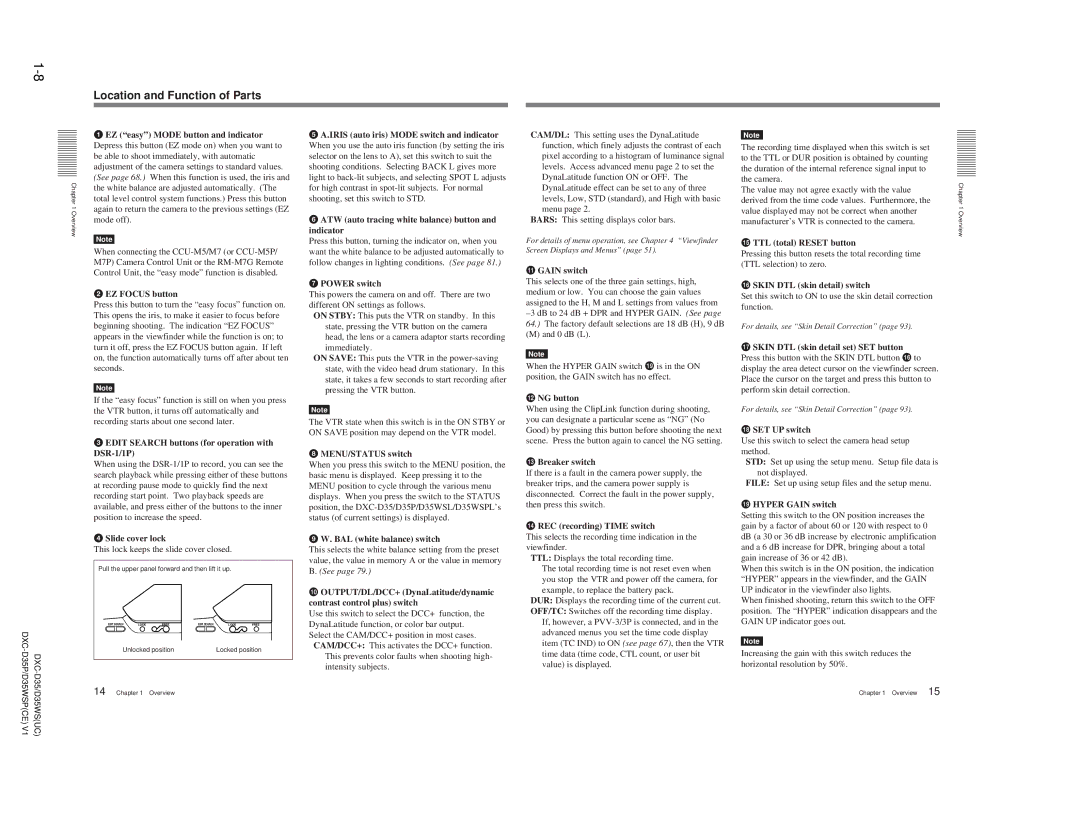
4Slide cover lock
This lock keeps the slide cover closed.
Pull the upper panel forward and then lift it up.
| EDIT SEARCH | LOCK | FREE | EDIT SEARCH | LOCK | FREE |
| Unlocked position |
| Locked position | |||
14 | Chapter 1 | Overview |
|
|
| |
5A.IRIS (auto iris) MODE switch and indicator When you use the auto iris function (by setting the iris selector on the lens to A), set this switch to suit the shooting conditions. Selecting BACK L gives more light to
6ATW (auto tracing white balance) button and indicator
Press this button, turning the indicator on, when you want the white balance to be adjusted automatically to follow changes in lighting conditions. (See page 81.)
7POWER switch
This powers the camera on and off. There are two different ON settings as follows.
ON STBY: This puts the VTR on standby. In this state, pressing the VTR button on the camera head, the lens or a camera adaptor starts recording immediately.
ON SAVE: This puts the VTR in the
Note
The VTR state when this switch is in the ON STBY or ON SAVE position may depend on the VTR model.
8MENU/STATUS switch
When you press this switch to the MENU position, the basic menu is displayed. Keep pressing it to the MENU position to cycle through the various menu displays. When you press the switch to the STATUS position, the
9W. BAL (white balance) switch
This selects the white balance setting from the preset value, the value in memory A or the value in memory B. (See page 79.)
0OUTPUT/DL/DCC+ (DynaLatitude/dynamic contrast control plus) switch
Use this switch to select the DCC+ function, the DynaLatitude function, or color bar output. Select the CAM/DCC+ position in most cases.
CAM/DCC+: This activates the DCC+ function. This prevents color faults when shooting high- intensity subjects.
CAM/DL: This setting uses the DynaLatitude function, which finely adjusts the contrast of each pixel according to a histogram of luminance signal levels. Access advanced menu page 2 to set the DynaLatitude function ON or OFF. The DynaLatitude effect can be set to any of three levels, Low, STD (standard), and High with basic menu page 2.
BARS: This setting displays color bars.
For details of menu operation, see Chapter 4 “Viewfinder Screen Displays and Menus” (page 51).
qa GAIN switch
This selects one of the three gain settings, high, medium or low. You can choose the gain values assigned to the H, M and L settings from values from
(M) and 0 dB (L).
Note
When the HYPER GAIN switch ql is in the ON position, the GAIN switch has no effect.
qs NG button
When using the ClipLink function during shooting, you can designate a particular scene as “NG” (No Good) by pressing this button before shooting the next scene. Press the button again to cancel the NG setting.
qd Breaker switch
If there is a fault in the camera power supply, the breaker trips, and the camera power supply is disconnected. Correct the fault in the power supply, then press this switch.
qf REC (recording) TIME switch
This selects the recording time indication in the viewfinder.
TTL: Displays the total recording time.
The total recording time is not reset even when you stop the VTR and power off the camera, for example, to replace the battery pack.
DUR: Displays the recording time of the current cut.
OFF/TC: Switches off the recording time display. If, however, a
Note
The recording time displayed when this switch is set to the TTL or DUR position is obtained by counting the duration of the internal reference signal input to the camera.
The value may not agree exactly with the value derived from the time code values. Furthermore, the value displayed may not be correct when another manufacturer’s VTR is connected to the camera.
qg TTL (total) RESET button
Pressing this button resets the total recording time (TTL selection) to zero.
qh SKIN DTL (skin detail) switch
Set this switch to ON to use the skin detail correction function.
For details, see “Skin Detail Correction” (page 93).
qj SKIN DTL (skin detail set) SET button
Press this button with the SKIN DTL button qh to display the area detect cursor on the viewfinder screen. Place the cursor on the target and press this button to perform skin detail correction.
For details, see “Skin Detail Correction” (page 93).
qk SET UP switch
Use this switch to select the camera head setup method.
STD: Set up using the setup menu. Setup file data is not displayed.
FILE: Set up using setup files and the setup menu.
ql HYPER GAIN switch
Setting this switch to the ON position increases the gain by a factor of about 60 or 120 with respect to 0 dB (a 30 or 36 dB increase by electronic amplification and a 6 dB increase for DPR, bringing about a total gain increase of 36 or 42 dB).
When this switch is in the ON position, the indication “HYPER” appears in the viewfinder, and the GAIN UP indicator in the viewfinder also lights.
When finished shooting, return this switch to the OFF position. The “HYPER” indication disappears and the GAIN UP indicator goes out.
Note
Increasing the gain with this switch reduces the horizontal resolution by 50%.
Chapter 1 Overview 15
Chapter 1 Overview