3-3-3. Y/R-Y/B-Y CLP Level Adjustment
Equipment: | Oscilloscope |
To be extended: | |
| |
Preparation: | OUTPUT/DL/DCC +switch: BARS |
Test point: | TP60, 61, 62 (GND: TP63) |
| |
Trigger: | HD |
Adjustment Procedure
1.Select “PAGE 10” of SERVICE menu, make sure that
2.SERVICE menu “PAGE 6”
→Y CLP: R-Y CLP: B-Y CLP:
3.Adjust the following items by UP ![]() switch or DOWN
switch or DOWN
![]() switch to meet the specification.
switch to meet the specification.
n
In case of Y CLP for NTSC model, perform the adjustment as follows.
1Select “PAGE 9” of SERVICE menu, and set the “SETUP” to “OFF”.
2Select “PAGE 6” of SERVICE menu, and move the cursor to Y CLP.
3Adjustment: A = 0 ±5 mV
4Select “PAGE 9” of SERVICE menu, and set the “SETUP” to “ON”.
5And return to “PAGE 6”.
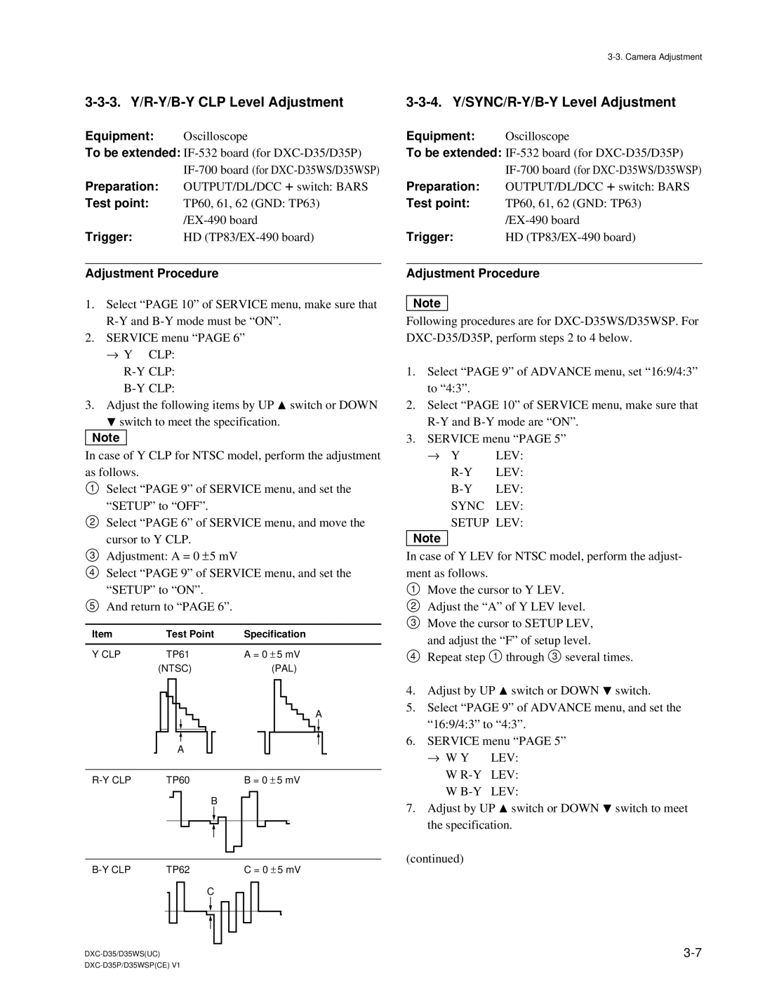
Item | Test Point | Specification |
|
|
|
Y CLP | TP61 | A = 0 ± 5 mV |
| (NTSC) | (PAL) |
A
A
TP60 |
|
|
|
|
|
|
| B = 0 ± 5 mV | |||||||||||||||
|
|
|
|
|
|
|
|
| B |
|
|
|
| ||||||||||
|
|
|
|
|
|
|
|
|
|
|
|
|
|
|
|
|
| ||||||
|
|
|
|
|
|
|
|
|
|
|
|
|
|
|
|
| |||||||
|
|
|
|
|
|
|
|
|
|
|
|
|
|
|
|
|
|
|
|
|
|
|
|
|
|
|
|
|
|
|
|
|
|
|
|
|
|
|
|
|
|
|
|
|
|
|
|
|
|
|
|
|
|
|
|
|
|
|
|
|
|
|
|
|
|
|
|
|
|
|
|
|
|
|
|
|
|
|
|
|
|
|
|
|
|
|
|
|
|
|
|
|
|
|
|
|
|
|
|
|
|
|
|
|
|
|
|
|
|
|
|
|
|
|
|
|
|
|
|
TP62 |
|
|
|
|
|
|
| C = 0 ± 5 mV | |||||||||||||||
|
|
|
|
|
|
|
| C | |||||||||||||||
|
|
|
|
|
|
|
|
|
|
|
|
|
|
|
|
|
|
|
|
|
|
|
|
|
|
|
|
|
|
|
|
|
|
|
|
|
|
|
|
|
|
|
|
|
|
|
|
3-3-4. Y/SYNC/R-Y/B-Y Level Adjustment
Equipment: | Oscilloscope |
To be extended: | |
| |
Preparation: | OUTPUT/DL/DCC +switch: BARS |
Test point: | TP60, 61, 62 (GND: TP63) |
| |
Trigger: | HD |
Adjustment Procedure
n
Following procedures are for
1.Select “PAGE 9” of ADVANCE menu, set “16:9/4:3” to “4:3”.
2.Select “PAGE 10” of SERVICE menu, make sure that
3.SERVICE menu “PAGE 5”
→Y LEV:
R-Y LEV:
SYNC LEV: SETUP LEV:
n
In case of Y LEV for NTSC model, perform the adjust- ment as follows.
1Move the cursor to Y LEV.
2 Adjust the “A” of Y LEV level.
3 Move the cursor to SETUP LEV,
and adjust the “F” of setup level.
4 Repeat step 1 through 3 several times.
4.Adjust by UP ![]() switch or DOWN
switch or DOWN ![]() switch.
switch.
5.Select “PAGE 9” of ADVANCE menu, and set the “16:9/4:3” to “4:3”.
6.SERVICE menu “PAGE 5”
→ W Y | LEV: |
W | LEV: |
W | LEV: |
7.Adjust by UP ![]() switch or DOWN
switch or DOWN ![]() switch to meet the specification.
switch to meet the specification.
(continued)