3-3. Camera Adjustment
n
Before the adjustment, enter the “PAGE 1” of SERVICE menu, and perform the “RESET”.
3-3-1. Sub-Carrier Frequency Adjustment
Equipment: | Frequency counter |
To be extended: | |
| |
Test point: | TP501 (GND: E501) |
| |
| |
Adjusting point: SERVICE menu “PAGE 8”
→SC FREQ:
Adjust the ![]() switch or DOWN
switch or DOWN ![]() switch to meet the specification.
switch to meet the specification.
Specification: 3,579,545 ± 10 Hz (for NTSC) 4,433,618 ± 10 Hz (for PAL)
3-3-2. INT SC-H Phase Adjustment
n
Stated below is a procedure with the
If any other equipment is used, perform adjustment at the following adjustment point by reading the instruction manual attached.
Equipment: Waveform monitor
Preparation:
.Put the Tektronix Waveform monitor 1765 to
Test point: VIDEO OUT connector
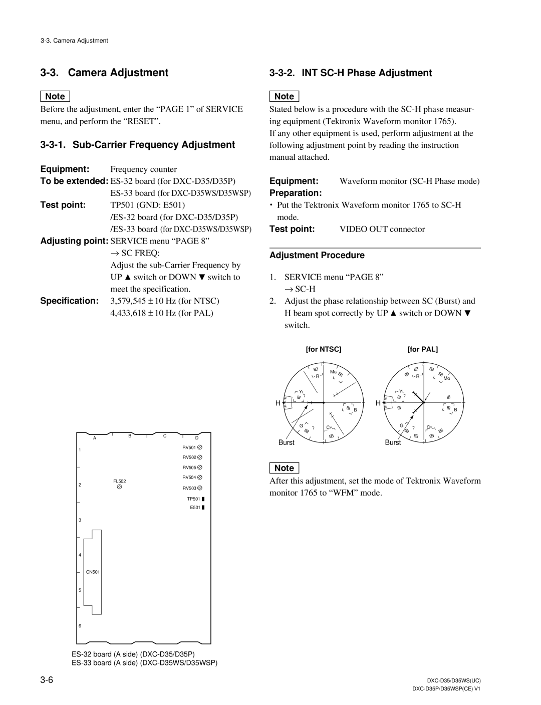
Adjustment Procedure
1.SERVICE menu “PAGE 8” →
2.Adjust the phase relationship between SC (Burst) and H beam spot correctly by UP ![]() switch or DOWN
switch or DOWN ![]() switch.
switch.
1
2
3
4
5
6
AB
FL502
CN501
CD
RV501 ![]() RV502
RV502 ![]() RV505
RV505 ![]() RV504
RV504 ![]() RV503
RV503 ![]()
TP501 ![]()
![]()
E501 ![]()
![]()
| [for NTSC] |
| [for PAL] |
|
| MG |
| R |
|
| R |
| MG | |
|
|
|
| |
YL |
| YL |
|
|
H |
| H |
| B |
| B |
|
| |
G | CY | G | CY |
|
|
|
| ||
Burst |
| Burst |
|
|
n
After this adjustment, set the mode of Tektronix Waveform monitor 1765 to “WFM” mode.