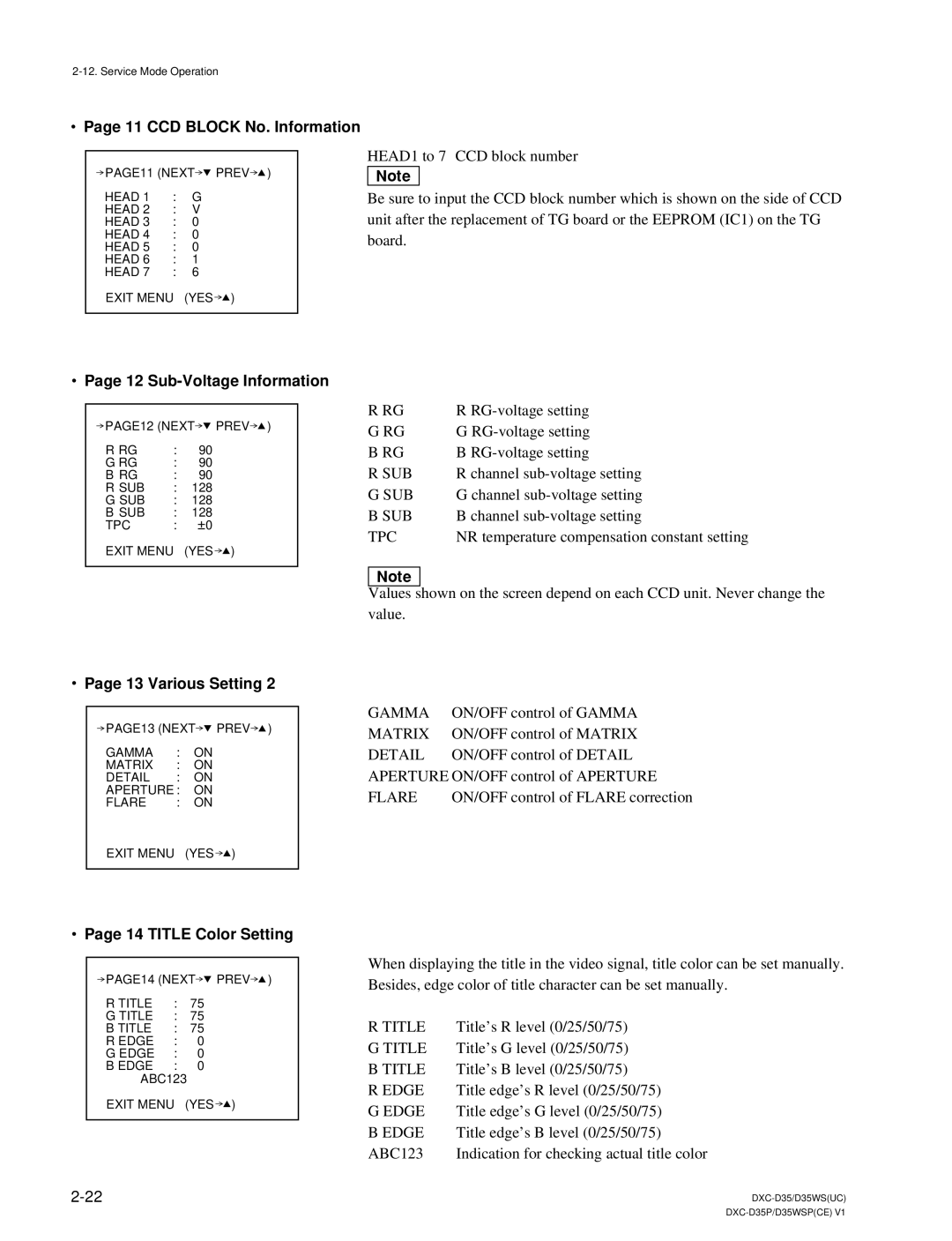
.Page 11 CCD BLOCK No. Information
PAGE11 (NEXT![]() PREV
PREV![]() )
)
HEAD 1 | : | G |
HEAD 2 | : | V |
HEAD 3 | : | 0 |
HEAD 4 | : | 0 |
HEAD 5 | : | 0 |
HEAD 6 | : | 1 |
HEAD 7 | : | 6 |
EXIT MENU (YES ![]() )
)
HEAD1 to 7 CCD block number
n
Be sure to input the CCD block number which is shown on the side of CCD unit after the replacement of TG board or the EEPROM (IC1) on the TG board.
.Page 12 Sub-Voltage Information
PAGE12 (NEXT![]() PREV
PREV![]() )
)
R RG | : | 90 |
G RG | : | 90 |
B RG | : | 90 |
R SUB | : | 128 |
G SUB | : | 128 |
B SUB | : | 128 |
TPC | : | ±0 |
EXIT MENU (YES ![]() )
)
.Page 13 Various Setting 2
R RG | R |
G RG | G |
B RG | B |
R SUB | R channel |
G SUB | G channel |
B SUB | B channel |
TPC | NR temperature compensation constant setting |
n
Values shown on the screen depend on each CCD unit. Never change the value.
PAGE13 (NEXT![]() PREV
PREV![]() )
)
GAMMA | : | ON |
MATRIX | : | ON |
DETAIL | : | ON |
APERTURE : | ON | |
FLARE | : | ON |
EXIT MENU (YES ![]() )
)
.Page 14 TITLE Color Setting
PAGE14 (NEXT![]() PREV
PREV![]() )
)
R TITLE | : | 75 |
G TITLE | : | 75 |
B TITLE | : | 75 |
R EDGE | : | 0 |
G EDGE | : | 0 |
B EDGE | : | 0 |
ABC123 |
| |
EXIT MENU (YES ![]() )
)
GAMMA | ON/OFF control of GAMMA |
MATRIX | ON/OFF control of MATRIX |
DETAIL | ON/OFF control of DETAIL |
APERTURE ON/OFF control of APERTURE | |
FLARE | ON/OFF control of FLARE correction |
When displaying the title in the video signal, title color can be set manually. Besides, edge color of title character can be set manually.
R TITLE | Title’s R level (0/25/50/75) |
G TITLE | Title’s G level (0/25/50/75) |
B TITLE | Title’s B level (0/25/50/75) |
R EDGE | Title edge’s R level (0/25/50/75) |
G EDGE | Title edge’s G level (0/25/50/75) |
B EDGE | Title edge’s B level (0/25/50/75) |
ABC123 | Indication for checking actual title color |
