3-3-9. Chroma (YC) Level Adjustment
Equipment: | Oscilloscope |
To be extended: | |
| |
Preparation: | OUTPUT/DL/DCC +switch: BARS |
Test point: | TP64 (GND: |
Trigger: | HD |
Adjusting point: 1RV505 (CHROMA (YC)
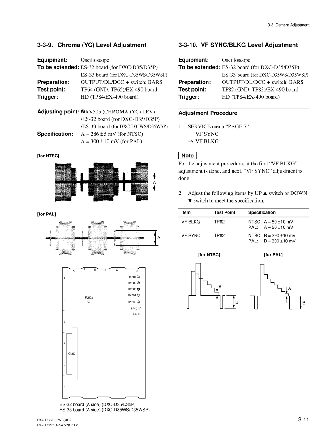
Specification: A = 286 ± 5 mV (for NTSC) A = 300 ± 10 mV (for PAL)
[for NTSC]
[for PAL]
3-3-10. VF SYNC/BLKG Level Adjustment
Equipment: | Oscilloscope |
To be extended: | |
| |
Preparation: | OUTPUT/DL/DCC +switch: BARS |
Test point: | TP82 (GND: |
Trigger: | HD |
Adjustment Procedure
1.SERVICE menu “PAGE 7”
VF SYNC
→VF BLKG
n
For the adjustment procedure, at the first “VF BLKG” adjustment is done, and next, “VF SYNC” adjustment is done.
2.Adjust the following items by UP ![]() switch or DOWN
switch or DOWN
![]() switch to meet the specification.
switch to meet the specification.
Item | Test Point | Specification |
| |
|
|
|
| |
VF BLKG | TP82 | NTSC: A = 50 | ±10 mV | |
|
| PAL: | A = 50 | ±10 mV |
|
|
|
| |
VF SYNC | TP82 | NTSC: | B = 290 ±10 mV | |
|
| PAL: | B = 300 ±10 mV | |
[for NTSC] |
| [for PAL] | ||
1
2
3
4
5
6
AB
FL502
CN501
CD
RV501 ![]() RV502
RV502 ![]() RV505
RV505 ![]() RV504
RV504 ![]() RV503
RV503 ![]()
TP501 ![]()
![]()
E501 ![]()
![]()
A |
| A | ||||||||
| ||||||||||
|
|
|
|
|
|
|
|
|
|
|
|
|
| B |
|
|
| B | |||
|
|
|
|
|
| |||||
|
|
|
|
|
|
|
|
|
|
|