3-2. Before Adjustment
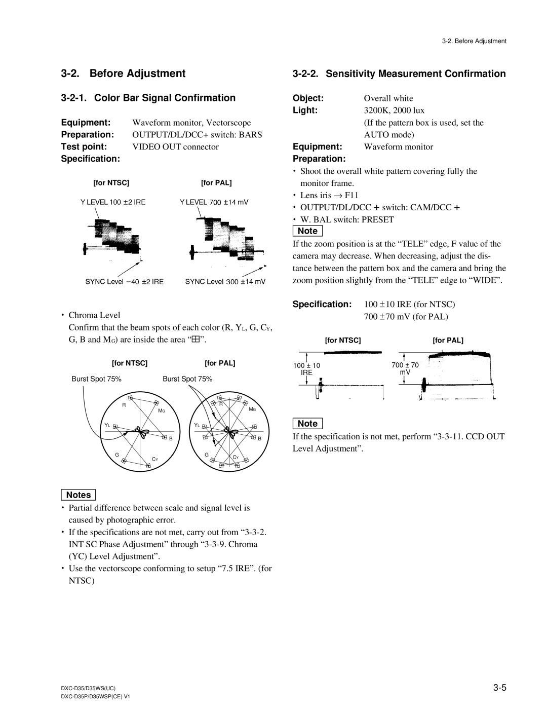
3-2-1. Color Bar Signal Confirmation
Equipment: Waveform monitor, Vectorscope
Preparation: OUTPUT/DL/DCC+ switch: BARS
Test point: VIDEO OUT connector
Specification:
[for NTSC] | [for PAL] |
.Chroma Level
Confirm that the beam spots of each color (R, YL, G, CY, G, B and MG) are inside the area “ 4”.
[for NTSC] |
| [for PAL] |
| |
Burst Spot 75% |
| Burst Spot 75% |
|
|
R |
| MG | R | MG |
|
|
| ||
|
|
|
| |
YL |
| YL |
|
|
|
| B |
| B |
G | CY | G | CY |
|
|
|
| ||
|
|
|
| |
3-2-2. Sensitivity Measurement Confirmation
Object: | Overall white |
Light: | 3200K, 2000 lux |
| (If the pattern box is used, set the |
| AUTO mode) |
Equipment: | Waveform monitor |
Preparation: |
|
.Shoot the overall white pattern covering fully the monitor frame.
.Lens iris → F11
.OUTPUT/DL/DCC +switch: CAM/DCC +
.W. BAL switch: PRESET n
If the zoom position is at the “TELE” edge, F value of the camera may decrease. When decreasing, adjust the dis- tance between the pattern box and the camera and bring the zoom position slightly from the “TELE” edge to “WIDE”.
Specification: 100 ± 10 IRE (for NTSC) 700 ± 70 mV (for PAL)
[for NTSC] | [for PAL] |
n
If the specification is not met, perform
m
.Partial difference between scale and signal level is caused by photographic error.
.If the specifications are not met, carry out from
.Use the vectorscope conforming to setup “7.5 IRE”. (for NTSC)
