3-3-6. Chroma (VBS) Level Adjustment
n
Use the vectorscope conforming to setup “7.5 IRE”. (for NTSC)
Equipment: Verctorscope
To be extended:
Preparation:
.GAIN switch/Verctorscope: 75 % CAL
.Adjust the PHASE control on the vectorscope so that the burst spot is overlapped to the 75 % axis.
.OUTPUT/DL/DCC +switch: BARS
Test point: VIDEO OUT connector
Adjustment Procedure
1.[for NTSC]
SERVICE menu “PAGE 7” →
Adjust by the UP ![]() switch or DOWN
switch or DOWN ![]() switch so that burst spot is located at 75 % scale mark on the vector- scope screen.
switch so that burst spot is located at 75 % scale mark on the vector- scope screen.
(In case of NTSC, make sure that
[for PAL]
SERVICE menu “PAGE 7”
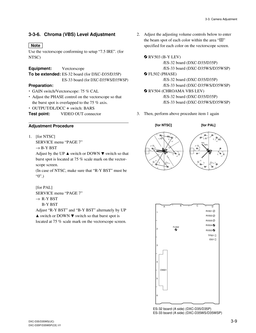
2.Adjust the adjusting volume controls below to enter the beam spot of each color within the area “ 4” specified for each color on the vectorscope screen.
1RV503
1FL502 (PHASE)
1RV504 (CHROAMA VBS LEV)
3. Then, perform above procedure item 1 again
| [for NTSC] |
| [for PAL] |
|
| MG |
| R |
|
| R |
| MG | |
|
|
|
| |
|
|
| 75% |
|
YL |
| YL | 100% |
|
|
|
| ||
| B |
|
| B |
G | CY | G | CY |
|
|
|
|
→R-Y BST B-Y BST
Adjust ![]() switch or DOWN
switch or DOWN ![]() switch so that burst spot is
switch so that burst spot is
located at 75 % scale mark on the vectorscope screen.
1
2
3
4
5
6
AB
FL502
CN501
CD
RV501 ![]() RV502
RV502 ![]() RV505
RV505 ![]() RV504
RV504 ![]() RV503
RV503 ![]()
TP501 ![]()
![]()
E501 ![]()
![]()