Contents
Power Macintosh/Performa 5200 and 5300 not 5260
Basics
System Overview
Rev. B, 5000 Series
Page
Performa 5320CD
Open Transport
Ordering
Service Strategy
Warranty and AppleCare
Design for Serviceability
Diagnostics
User Controls
Internal Expansion Connections
Intelligent Device Electronics IDE Hard Drive
Processor Direct Slot PDS
Video-In Card
Mpeg Card
TV Tuner Module
TV/FM Radio Tuner Card
Page
Page
Page
External Video Connector
Apple Presentation System
CRT and Degauss Frame
Front View
Rear View
Panel
Logic Board
ROM
Specifications
CPU
Processor
Dram
Memory
ROM
Floppy Drive Hard Drive
Disk Storage
Interfaces
Sound Output
Communications
Devices
Sound Generator
Sound and Video
Built-in Video
Video Modes
Monitor Timings 640x480 Resolution At 60 Hz
Monitor Timings 640x480 Resolution At 66.67 Hz
Monitor Timings 800x600 Resolution At 60 Hz
Monitor Timings 800x600 Resolution At 72 Hz
External Video
Electrical
Physical
Weight
Environmental
Temperature
Troubleshooting
General
First Checklist
System
Symptom Charts
ROM Dimm
Replace power supply
Page
Identifying Version B Logic Boards
Page
Audio
Page
Video
Page
Picture
Screen
Page
Page
Page
Floppy Drive
Page
Hard Drive
CD-ROM Drive
Page
Page
Peripheral
Cannot
Page
Miscellaneous
Screen
Page
Page
Global Village Modem Busy Serial Port
Page
Take Apart
Drive and Control Bezel
Page
Replacement Note
Floppy Drive
Page
Page
Page
CD-ROM Drive
Page
Page
Replacement Note
Front Panel Control Board
Page
Using
Tilt Board up slightly to Insert it into the guide rails
Front edge of the reinstalled
Door
Take Apart Door Remove the two security Screws
Align
Take Apart Logic Board
Page
Page
Page
You
Page
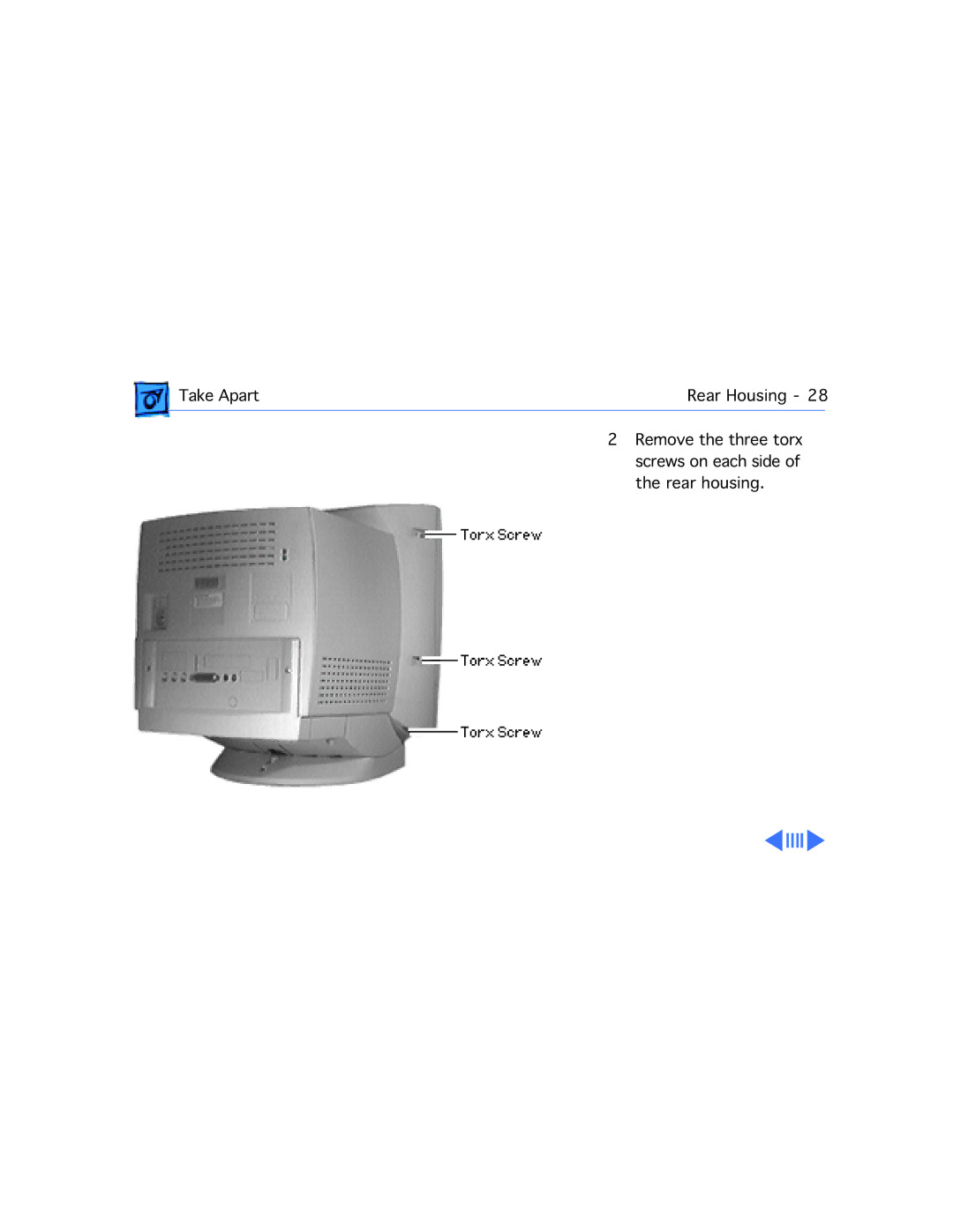
Rear Housing
Page
Page
±Warning This step
Front Bezel
Page
Page
Take Apart Front Bezel
Internal Microphone
Take Apart Internal Microphone LIft off the microphone
Rear EMI Shield
Page
Page
Insert the two corner
Speakers, Original Version
Page
Take Apart Speakers, Original Version Follow the procedures
Take Apart Speakers, Original Version
Speakers Rev. B
Page
Page
Take Apart Speakers, Rev. B Tilt the speaker Remove it
Take Apart Speakers, Rev. B
Take Apart Hard Drive
Page
Replacement Caution
Page
TV Tuner
Page
Page
Power Supply Rev. a
Supply
Page
Power Supply EMI Shield Screw
Interlocking Tab Power Supply EMI Shield
Ground Cable Screw
Supply board to
Pin Degauss Cable
Page
Page
This
CN7 Pin degauss cable
Power Supply Rev. B
Supply, Rev. a but use
Take Apart Power Supply, Rev. B
Video Board
±Warning
Take Apart
Page
Analog Shield
Analog board shield
Interlocking tabs
Analog Board Original Version
Page
Page
Page
Important At this
Page
From the analog board
Take Apart Analog Board, Original Version
Analog Board Rev. B
Page
Take Apart Analog Board, Rev. B Disconnect these video board
Take Apart Analog Board, Rev. B Disconnect these cables
Internal RGB Cable
Take Apart Internal RGB Cable
Fan
Take Apart Fan
Take Apart Fan Remove the fan security Screw
Page
Tilt/Swivel Base
Page
Replacement Note
CRT
Take Apart CRT
±Warning
Page
Page
Take Apart CRT
Chassis/Wiring Harness
Page
Page
Upgrades
TV or TV/FM Tuner
Page
Page
Simm
Upgrade
On both sides of the Simm
Upgrades5300 Simm Upgrade
±Replacement Warning
Upgrades Simm Upgrade
Remove the heat sink From the component side Logic board
Install the Simm Slot next to Processor
Communications Card Installation
Upgrades Communications Card Installation
Through
Replacement Note If you
Insert the card connector
UpgradesExternal Video Connector
Upgrades External Video Connector
Upgrades External Video Connector Remove the plastic
Upgrades External Video Connector Insert the slotted metal
Upgrades External Video Connector Insert the connector end
Page
L2 Cache
Installation
LC PDS Card
Additional Procedures
Battery Verification
Negative Positive Probe Probe
Battery Replacement
Page
Logic Board Reset
Page
Page
Page
REA Procedures
Repair Overview for Freezing Video Color Hue Issues
Power Mac/Performa 52xx
Page
Why Replace the EMI Clips?
Why Replace the Logic Board/ROM DIMM?
Why Replace the Ethernet Card Fence?
Why Replace the Internal RGB Cable?
System Tester
Page
Page
Part Numbers
Page
Before You Begin
Remove the 52xx, 53xx I/O Door
Repair Procedures
Inspect the Logic Board
You’re replacing the Cache/ROM Dimm Otherwise go to step
ROM Dimm
Replace the Cache
Go to step
Replace the Logic Board
Fence to the solder side
Page
Transfer the Double- Sided Dram Simm
Double-Sided
Upgrade RAM for Education Customers
Card Fence
Replace the Ethernet
REA Procedures Repair Procedures
REA Procedures Repair Procedures
Replace the EMI Clips
Squeeze
Bottom Logic Board Clip Opening Clip Base
Remove the Rear Housing
±Warning The Power
Tip Pry up from the rear
Inspect the Internal RGB Cable
Repairs. Go to step
Remove the Rear EMI Shield
Discharge the CRT
Page
Pull off the Video Board
When you reinstall
Tilt Back the Analog Board and Shield
Replacement Note Be
Replace the Internal RGB Cable
Page
Test, Reassemble, Label the Unit
Label Location
Page
Install System
Page
Page
Adjustments
Model R77
Light Meter Setup
Page
Page
Page
Model L-248
Model
Geometry
5200/5300 Adjustments not for 5260 Geometry
Horizontal Shift
Centering switch
Vertical Shift
Focus
On-Screen Video
± Warning Never use an
Remove the three
Remove the shunt that
Square
For Rev. B, connect
Placed on the pins
Yoke Aperture Anode Wires Flyback Transformer
Resolution screen
Page
Page
Video
Replacement Note Perform
Cutoff
5200/5300 Adjustments not for 5260 Video
CRT Video Board VR303 VR302
5200/5300 Adjustments not for 5260 Video
Screen Control Flyback Transformer
White Balance
5200/5300 Adjustments not for 5260 Video
Page
Screen
5200/5300 Adjustments not for 5260 Video
5200/5300 Adjustments not for 5260 Video
VR303 VR302 Gray Bars Test Pattern
Page
High Voltage
29.5
Voltmeter as follows
VR501 Rev. a Analog Board Inside
Rev. B Analog Board
Exploded View
Exploded View

