60 & 62 specifications
Aprilaire models 60 and 62 are advanced dehumidifiers designed to enhance indoor air quality by effectively controlling humidity levels. These units are particularly suitable for homes in regions where excess moisture can lead to mold growth, structural damage, and discomfort.Both the Aprilaire 60 and 62 feature a robust moisture removal system, capable of extracting up to 70 pints of moisture per day, depending on the model and conditions. This level of capacity ensures that even in significant humidity scenarios, your indoor environment remains comfortable and healthy.
One of the standout features of these dehumidifiers is their efficiency. The models utilize an Energy Star rating, which indicates they consume less energy while delivering optimal performance. This not only translates to reduced energy bills but also a lower environmental impact compared to less efficient units.
The technology used in Aprilaire dehumidifiers incorporates a built-in humidity control system. This allows users to set the desired humidity level, ensuring that the unit operates only when necessary. This automatic operation can prevent over-drying and maintain consistent humidity, which is crucial for both comfort and health.
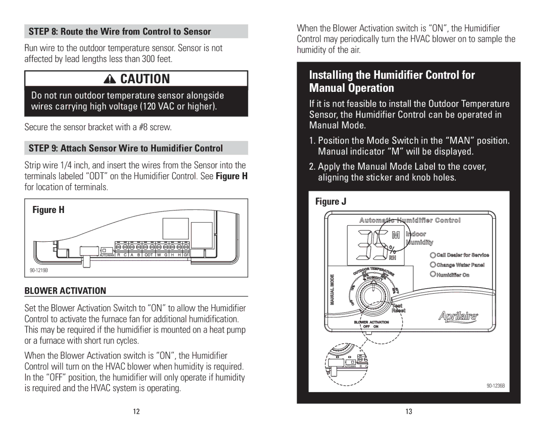
Additionally, both models are designed with user-friendly interfaces. They come equipped with digital displays showcasing real-time humidity levels, allowing homeowners to monitor conditions effortlessly. Furthermore, they feature continuous drainage options, meaning that they can be connected to a drainage system to eliminate the hassle of manual water removal.
The Aprilaire 60 and 62 also boast a durable design, built to withstand the rigors of regular use. Their compact size makes them easy to position in a variety of home settings, whether in basements, crawl spaces, or other areas prone to humidity buildup.
In summary, the Aprilaire 60 and 62 dehumidifiers represent cutting-edge technology in humidity control. With high moisture extraction capabilities, energy efficiency, and user-friendly operation, they are ideal solutions for maintaining an optimal home environment. Homeowners seeking a reliable and effective way to manage humidity levels will find these models to be an excellent investment for ensuring comfort and protecting their living spaces from moisture-related issues.

