8476 specifications
The Aprilaire 8476 is a smart thermostat designed to enhance home climate control while promoting energy efficiency. This advanced thermostat stands out with its innovative features and user-friendly design, making it a top choice for homeowners looking to optimize their indoor environment.One of the key features of the Aprilaire 8476 is its built-in Wi-Fi capability, which allows users to easily connect and control their home’s heating and cooling systems remotely via a smartphone or tablet. This connectivity ensures that users can adjust their home’s temperature settings anytime, anywhere, making it ideal for busy lifestyles.
The intuitive touchscreen interface offers easy navigation and clear visibility of current temperature settings and schedules. This modern design enhances user interaction, allowing for straightforward programming of heating and cooling schedules to suit individual preferences.
Energy efficiency is a top priority with the Aprilaire 8476. Its intelligent algorithms are designed to learn user habits over time, optimizing energy usage and reducing utility bills. The thermostat can provide energy reports and insights, helping homeowners make informed decisions about their energy consumption.
The Aprilaire 8476 also features advanced zoning capabilities, which means it can control multiple zones in a home independently. This feature ensures consistent comfort in different areas, allowing for customized climate control when needed.
For homes equipped with humidification systems, the Aprilaire 8476 integrates seamlessly, offering advanced humidity control. This capability helps maintain optimal indoor air quality and comfort levels, preventing issues associated with extreme dryness or humidity.
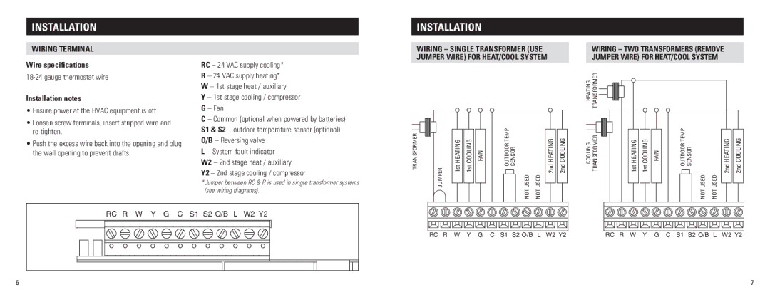
Compatibility is another strong point for the Aprilaire 8476, as it works with various HVAC systems, including conventional, heat pump, and multi-stage systems. This versatility means that homeowners do not need to worry about system incompatibilities when upgrading their thermostat.
In summary, the Aprilaire 8476 is an industry-leading smart thermostat that combines innovative technology with user-friendly features. Its Wi-Fi connectivity, touchscreen interface, energy efficiency practices, zoning capabilities, humidity control, and broad compatibility make it an excellent choice for homeowners seeking to enhance their comfort while reducing energy costs.

