The ‘Basic’ Set-up Menus
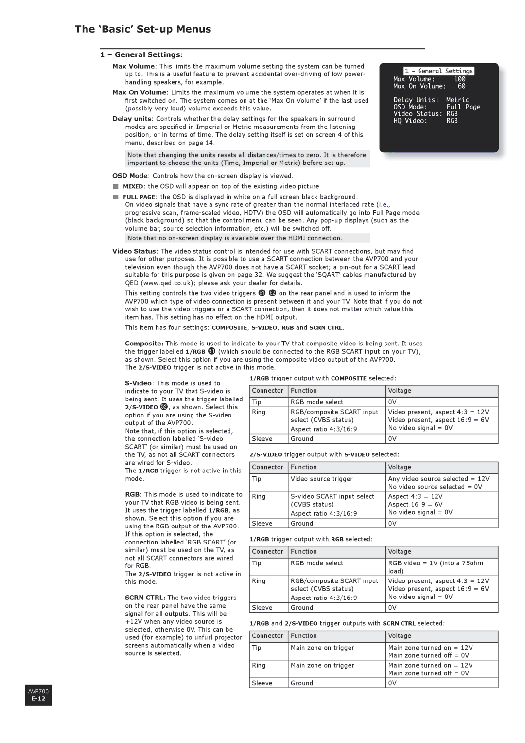
1 – General Settings:
Max Volume: This limits the maximum volume setting the system can be turned up to. This is a useful feature to prevent accidental
Max On Volume: Limits the maximum volume the system operates at when it is first switched on. The system comes on at the ‘Max On Volume’ if the last used (possibly very loud) volume exceeds this value.
Delay units: Controls whether the delay settings for the speakers in surround modes are specified in Imperial or Metric measurements from the listening position, or in terms of time. The delay setting itself is set on screen 4 of this menu, described on page 14.
Note that changing the units resets all distances/times to zero. It is therefore important to choose the units (Time, Imperial or Metric) before set up.
OSD Mode: Controls how the
<MIXED: the OSD will appear on top of the existing video picture
<FULL PAGE: the OSD is displayed in white on a full screen black background.
On video signals that have a sync rate of greater than the normal interlaced rate (i.e., progressive scan,
Note that no
Video Status: The video status control is intended for use with SCART connections, but may find use for other purposes. It is possible to use a SCART connection between the AVP700 and your television even though the AVP700 does not have a SCART socket; a
This setting controls the two video triggers fl fm on the rear panel and is used to inform the AVP700 which type of video connection is present between it and your TV. Note that if you do not wish to use the video triggers or a SCART connection, then it does not matter which value this item has. This setting has no effect on the HDMI output.
This item has four settings: COMPOSITE,
Composite: This mode is used to indicate to your TV that composite video is being sent. It uses the trigger labelled 1/RGB fl (which should be connected to the RGB SCART input on your TV), as shown. Select this option if you are using the composite video output of the AVP700.
The
Note that, if this option is selected, the connection labelled
The 1/RGB trigger is not active in this mode.
RGB: This mode is used to indicate to your TV that RGB video is being sent. It uses the trigger labelled 1/RGB, as shown. Select this option if you are using the RGB output of the AVP700. If this option is selected, the connection labelled ‘RGB SCART’ (or similar) must be used on the TV, as not all SCART connectors are wired for RGB.
The
SCRN CTRL: The two video triggers on the rear panel have the same signal for all outputs. This will be +12V when any video source is selected, otherwise 0V. This can be used (for example) to unfurl projector screens automatically when a video source is selected.
1/RGB trigger output with COMPOSITE selected:
Connector | Function | Voltage |
Tip | RGB mode select | 0V |
Ring | RGB/composite SCART input | Video present, aspect 4:3 = 12V |
| select (CVBS status) | Video present, aspect 16:9 = 6V |
| Aspect ratio 4:3/16:9 | No video signal = 0V |
Sleeve | Ground | 0V |
Connector | Function | Voltage |
Tip | Video source trigger | Any video source selected = 12V |
|
| No video source selected = 0V |
Ring | Aspect 4:3 = 12V | |
| (CVBS status) | Aspect 16:9 = 6V |
| Aspect ratio 4:3/16:9 | No video signal = 0V |
Sleeve | Ground | 0V |
1/RGB trigger output with RGB selected: |
| |
Connector | Function | Voltage |
Tip | RGB mode select | RGB video = 1V (into a 75ohm |
|
| load) |
Ring | RGB/composite SCART input | Video present, aspect 4:3 = 12V |
| select (CVBS status) | Video present, aspect 16:9 = 6V |
| Aspect ratio 4:3/16:9 | No video signal = 0V |
Sleeve | Ground | 0V |
1/RGB and | ||
Connector | Function | Voltage |
Tip | Main zone on trigger | Main zone turned on = 12V |
|
| Main zone turned off = 0V |
Ring | Main zone on trigger | Main zone turned on = 12V |
|
| Main zone turned off = 0V |
Sleeve | Ground | 0V |
AVP700