Pipe | Connect the cold water inlet pipe to the inlet nipple (marked with a blue ring - #1, Fig. 4). | |
Connections | IMPORTANT: You must use dielectric fittings if inlet piping/fittings are copper or brass. | |
| Failure to provide dielectric insulation may result in premature tank or nipple failure and will | |
| void warranty. Dielectric nipples are recommended over unions and are available from a | |
| supply house or CEC. | |
Caution | To | reduce the risk of excessive pressures and temperatures in this water heater, install |
| temperature and pressure protective equipment required by local codes but not less than a | |
| combination temperature and pressure relief valve certified by a nationally recognized | |
| testing laboratory that maintains periodic inspection of production of listed equipment or | |
| materials, as meeting the requirements for Relief Valves and Automatic Gas | |
| Devices for Hot Water Supply Systems, ANSI Z21.22. This valve must be marked with a | |
| maximum set pressure not to exceed the marked maximum working pressure of the water | |
| heater. Install the valve into the opening provided and marked for this purpose in the water | |
| heater, and orient it or provide tubing so that any discharge from the valve will exit within 6 | |
| inches above, or at any distance below, the structural floor, and cannot contact any live | |
| electrical part. The discharge opening must not be blocked or reduced in size under any | |
| circumstances. | |
Closed | Periodic discharge of the temperature and pressure relief valve or failure of the element | |
system | gasket may be due to thermal expansion in a closed water supply system. The water utility | |
thermal | supply meter may contain a check valve, backflow preventer or water pressure reducing | |
expansion | valve which will create a closed water system. During the heating cycle of the water heater, | |
| the water expands causing pressure inside the water heater to increase. The temperature | |
| and pressure relief valve may discharge hot water under these conditions which results in a | |
| loss of energy and a | |
| To prevent this from happening, there are two recommendations: | |
| 1. | Install a |
|
| water supply line. The expansion tank must have a minimum capacity of 1.5 U.S. |
|
| gallons for every 50 gallons of stored water. |
| 2. | Install a 125 PSI pressure relief valve in the cold water supply line. Make sure the |
|
| discharge of this valve is directed to an open drain and protected from freezing. |
|
| Contact the local water supplier or plumbing inspector for information on how to |
|
| control this situation. Do not plug the temperature and pressure relief valve. |
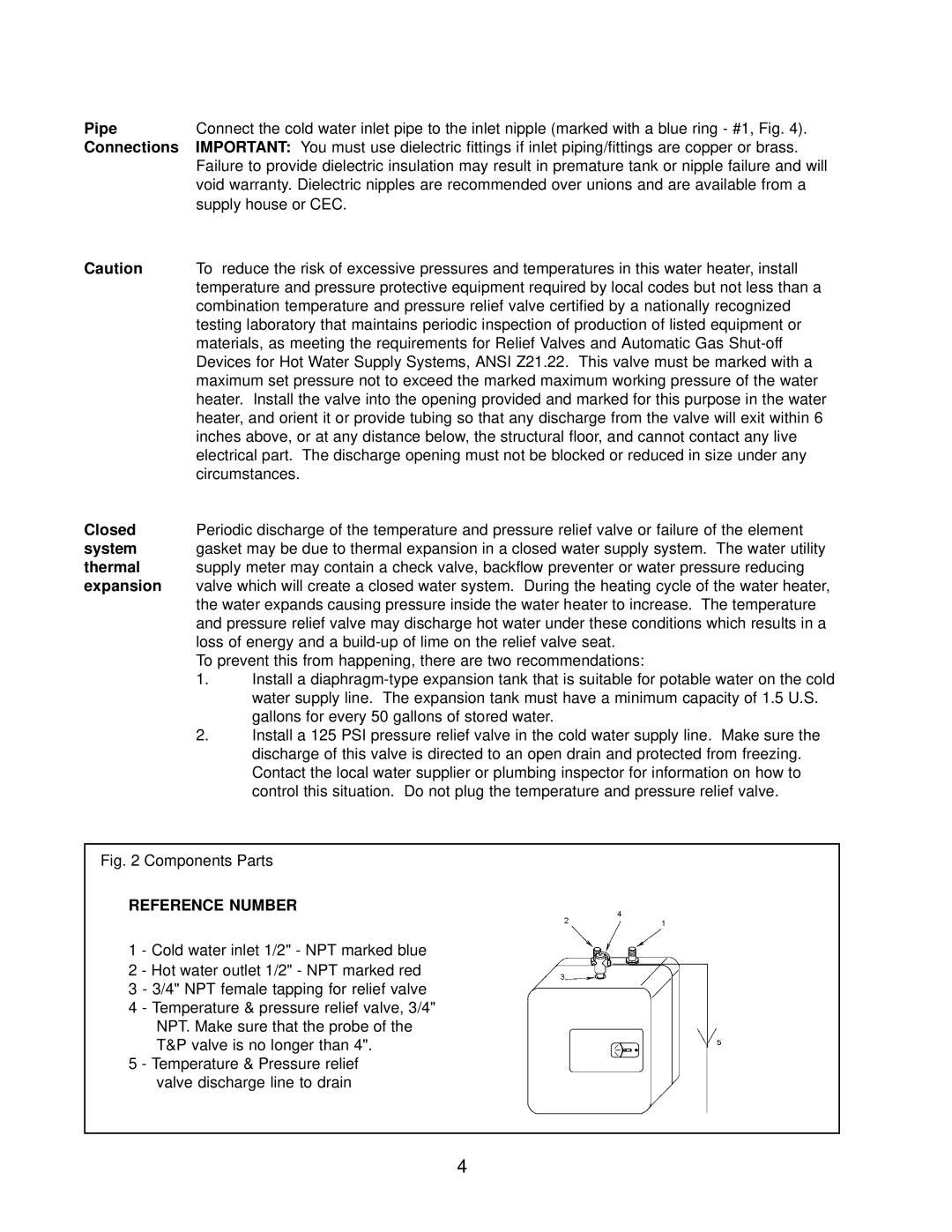
Fig. 2 Components Parts
REFERENCE NUMBER
1 - Cold water inlet 1/2" - NPT marked blue 2 - Hot water outlet 1/2" - NPT marked red
3 - 3/4" NPT female tapping for relief valve
4 - Temperature & pressure relief valve, 3/4" NPT. Make sure that the probe of the T&P valve is no longer than 4".
5 - Temperature & Pressure relief valve discharge line to drain
4
