MXM4425/G
Wiring
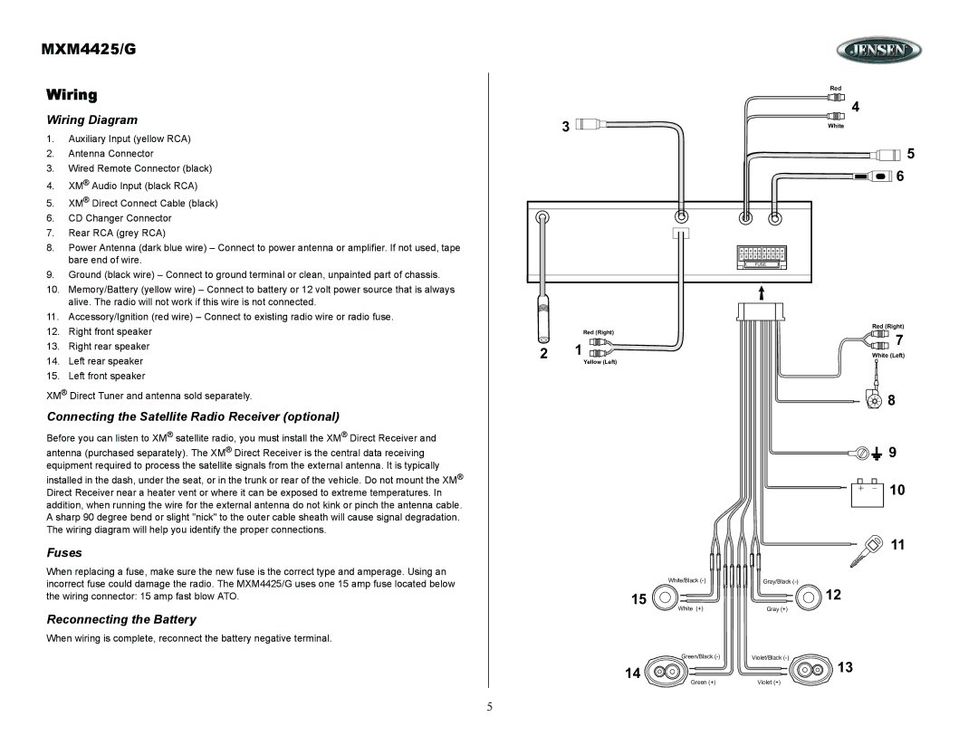
Wiring Diagram
1. | Auxiliary Input (yellow RCA) |
2. | Antenna Connector |
3. | Wired Remote Connector (black) |
4. | XM® Audio Input (black RCA) |
5. | XM® Direct Connect Cable (black) |
6. | CD Changer Connector |
7. | Rear RCA (grey RCA) |
8. | Power Antenna (dark blue wire) – Connect to power antenna or amplifier. If not used, tape |
| bare end of wire. |
9. | Ground (black wire) – Connect to ground terminal or clean, unpainted part of chassis. |
10. | Memory/Battery (yellow wire) – Connect to battery or 12 volt power source that is always |
| alive. The radio will not work if this wire is not connected. |
11. | Accessory/Ignition (red wire) – Connect to existing radio wire or radio fuse. |
Red
4
3 | White |
|
![]()
![]() 5
5 ![]() 6
6
FUSE
12. | Right front speaker |
13. | Right rear speaker |
14. | Left rear speaker |
15. | Left front speaker |
XM® Direct Tuner and antenna sold separately.
Connecting the Satellite Radio Receiver (optional)
Before you can listen to XM® satellite radio, you must install the XM® Direct Receiver and
antenna (purchased separately). The XM® Direct Receiver is the central data receiving equipment required to process the satellite signals from the external antenna. It is typically
installed in the dash, under the seat, or in the trunk or rear of the vehicle. Do not mount the XM® Direct Receiver near a heater vent or where it can be exposed to extreme temperatures. In addition, when running the wire for the external antenna do not kink or pinch the antenna cable. A sharp 90 degree bend or slight "nick" to the outer cable sheath will cause signal degradation. The wiring diagram will help you identify the proper connections.
Fuses
When replacing a fuse, make sure the new fuse is the correct type and amperage. Using an incorrect fuse could damage the radio. The MXM4425/G uses one 15 amp fuse located below the wiring connector: 15 amp fast blow ATO.
Reconnecting the Battery
When wiring is complete, reconnect the battery negative terminal.
Red (Right)
2 1
Yellow (Left)
White/Black
15
White (+)
Green/Black
14
Green (+)
Red (Right)
7
White (Left)
![]()
![]() 8
8
![]()
![]() 9
9
![]()
![]() +
+ ![]()
![]() 10
10
11
Gray/Black
12
Gray (+)
Violet/Black
13
Violet (+)
5