Operating Manual -
|
|
|
|
|
|
|
| G ain Reduction (d B) |
|
|
| ||||||
|
|
|
|
|
|
|
|
|
|
| |||||||
|
|
|
| Th. | 2 | 4 | 6 | 8 | 10 | 12 | 14 | 16 | 18 | 20 | |||
|
| 0 |
| 0 |
|
|
| 7 |
|
|
| 2 | 3 | ||||
| + 3 |
|
|
|
| 5 |
|
|
| 1 0 |
| 5 | |||||
|
|
| + 3 |
|
|
|
| 1 .5 |
| ||||||||
|
|
|
|
|
|
|
|
|
|
|
|
|
| ||||
+ 6 |
|
|
| + 6 | 3 |
|
|
|
| 2 0 |
| 1 0 | |||||
|
|
|
|
|
|
|
|
|
|
| |||||||
|
|
|
|
|
| + 1 0 |
|
|
|
|
|
| 1 |
|
| ||
+ 1 0 |
|
|
|
|
|
|
| 3 0 .5 |
| 1 5 | |||||||
|
|
| + 2 0 | 2 .5 |
|
| ∞ |
| |||||||||
|
|
|
|
|
|
|
|
|
|
|
|
| |||||
d B + 1 5 | d B + 2 2 |
| 2 |
|
|
|
| .2 | m S 2 0 | ||||||||
|
|
|
|
| Inpu t/Outpu t Level (dB) |
| C lip |
|
|
|
|
| |||
|
| +9 +20 |
|
|
|
|
| ||||||||
|
| .5 |
|
| 0 | + 3 |
|
|
|
|
|
|
| ||
.2 |
|
| 1 |
|
|
|
|
|
|
|
| Outpu t | |||
|
|
|
|
|
|
|
|
|
|
| |||||
|
|
|
|
| + 6 |
|
|
|
|
|
| ||||
|
|
|
|
|
|
|
|
|
|
|
|
| Inpu t | ||
|
|
|
|
|
|
| + 1 0 |
|
|
|
|
|
|
| |
|
|
|
|
|
|
|
|
|
|
|
|
|
| ||
|
|
|
|
|
|
|
|
|
|
|
|
|
|
| |
|
|
|
|
| 2 |
|
| + 1 5 |
|
|
|
|
|
|
|
|
|
|
|
|
|
|
|
|
|
|
|
|
| ||
.1 | S e c | 3 | d B | + 2 0 |
|
|
|
|
|
|
| ||||
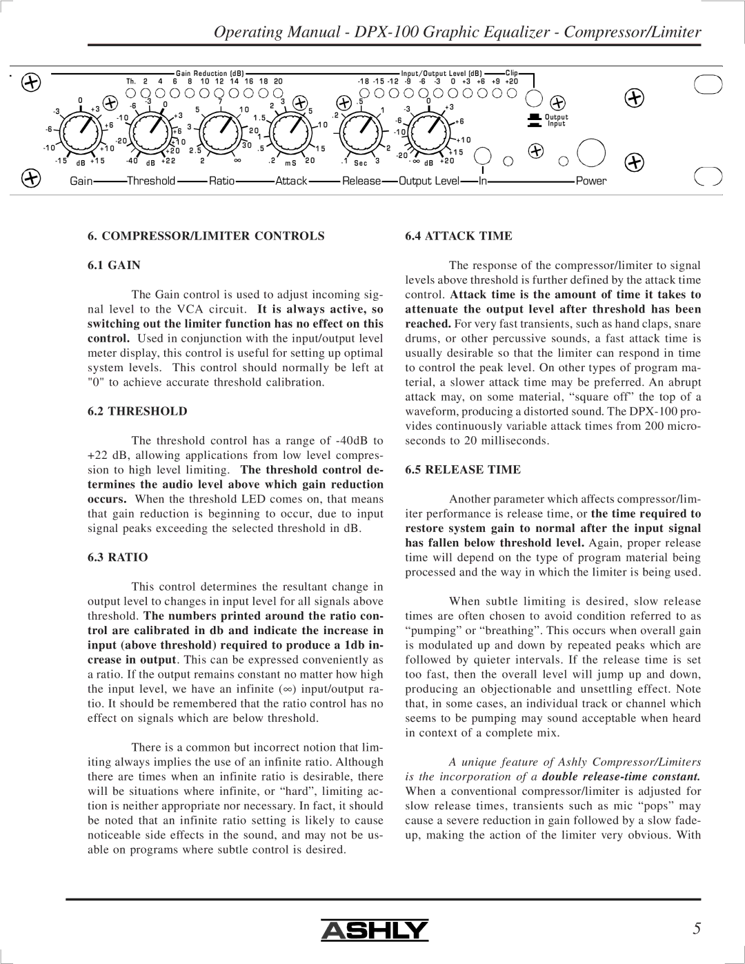
Gain |
| Threshold |
| Ratio |
| Attack |
| Release |
| Output Level |
| In |
| Power |
|
|
|
|
|
|
|
6.COMPRESSOR/LIMITER CONTROLS
6.1 GAIN
The Gain control is used to adjust incoming sig- nal level to the VCA circuit. It is always active, so
switching out the limiter function has no effect on this
control. Used in conjunction with the input/output level meter display, this control is useful for setting up optimal system levels. This control should normally be left at "0" to achieve accurate threshold calibration.
6.2 THRESHOLD
The threshold control has a range of
termines the audio level above which gain reduction
occurs. When the threshold LED comes on, that means that gain reduction is beginning to occur, due to input signal peaks exceeding the selected threshold in dB.
6.3 RATIO
This control determines the resultant change in output level to changes in input level for all signals above threshold. The numbers printed around the ratio con- trol are calibrated in db and indicate the increase in input (above threshold) required to produce a 1db in- crease in output. This can be expressed conveniently as a ratio. If the output remains constant no matter how high the input level, we have an infinite (∞ ) input/output ra- tio. It should be remembered that the ratio control has no effect on signals which are below threshold.
There is a common but incorrect notion that lim- iting always implies the use of an infinite ratio. Although there are times when an infinite ratio is desirable, there will be situations where infinite, or “hard”, limiting ac- tion is neither appropriate nor necessary. In fact, it should be noted that an infinite ratio setting is likely to cause noticeable side effects in the sound, and may not be us- able on programs where subtle control is desired.
6.4 ATTACK TIME
The response of the compressor/limiter to signal levels above threshold is further defined by the attack time
control. Attack time is the amount of time it takes to attenuate the output level after threshold has been
reached. For very fast transients, such as hand claps, snare drums, or other percussive sounds, a fast attack time is usually desirable so that the limiter can respond in time to control the peak level. On other types of program ma- terial, a slower attack time may be preferred. An abrupt attack may, on some material, “square off” the top of a waveform, producing a distorted sound. The
6.5 RELEASE TIME
Another parameter which affects compressor/lim- iter performance is release time, or the time required to
restore system gain to normal after the input signal
has fallen below threshold level. Again, proper release time will depend on the type of program material being processed and the way in which the limiter is being used.
When subtle limiting is desired, slow release times are often chosen to avoid condition referred to as “pumping” or “breathing”. This occurs when overall gain is modulated up and down by repeated peaks which are followed by quieter intervals. If the release time is set too fast, then the overall level will jump up and down, producing an objectionable and unsettling effect. Note that, in some cases, an individual track or channel which seems to be pumping may sound acceptable when heard in context of a complete mix.
A unique feature of Ashly Compressor/Limiters is the incorporation of a double
5