Operating Manual -
mpressor/Limiter |
|
|
|
|
|
|
|
| Graphic Equalizer |
|
| |
| PUSH |
| PUSH | |||||||||
tecto r Re turn/ D ucking Input |
|
|
|
|
|
| ||||||
|
|
|
|
|
|
|
|
|
| |||
Mono Plug For Ducking) |
|
|
|
|
|
|
|
|
|
| ||
ING = D etecto r S end |
|
|
|
|
|
|
|
|
|
| ||
|
|
|
|
|
| Chain |
|
| ||||
|
|
|
|
| ||||||||
D etector
![]() Input
Input![]()
![]() In
In ![]() O ut
O ut
![]() Output
Output![]()
![]() Input
Input![]()
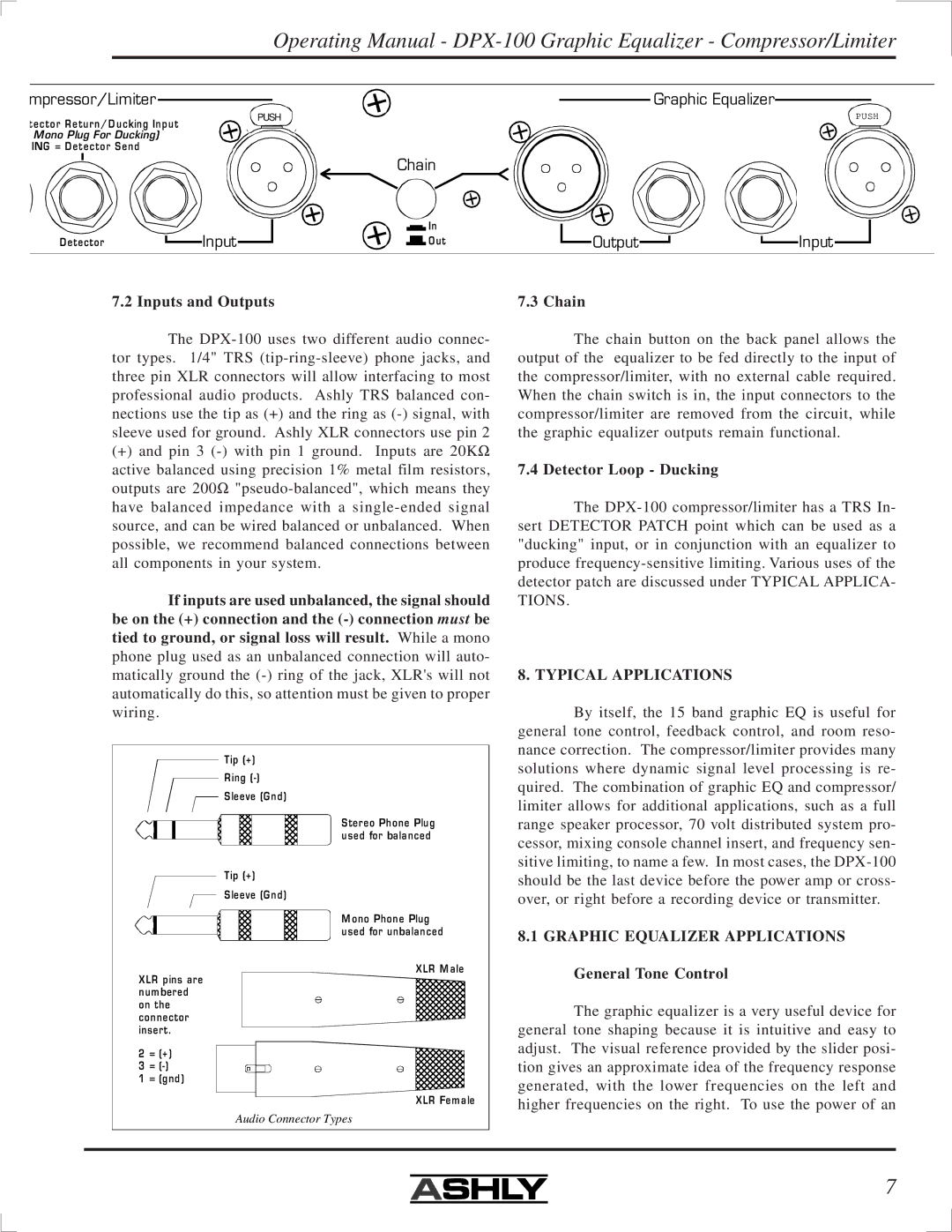
7.2 Inputs and Outputs
The
(+)and pin 3
active balanced using precision 1% metal film resistors, outputs are 200Ω
have balanced impedance with a
If inputs are used unbalanced, the signal should be on the (+) connection and the
Tip (+)
Ring
S leeve (Gnd)
S tereo Phone Plug used for balanced
Tip (+)
S leeve (Gnd)
M ono Phone Plug used for unbalanced
XLR M ale
XLR pins are num bered on the connector insert.
2 = (+ )
3 =
1 = (gnd)
XLR Fem ale
Audio Connector Types
7.3 Chain
The chain button on the back panel allows the output of the equalizer to be fed directly to the input of the compressor/limiter, with no external cable required. When the chain switch is in, the input connectors to the compressor/limiter are removed from the circuit, while the graphic equalizer outputs remain functional.
7.4 Detector Loop - Ducking
The
TIONS.
8. TYPICAL APPLICATIONS
By itself, the 15 band graphic EQ is useful for general tone control, feedback control, and room reso- nance correction. The compressor/limiter provides many solutions where dynamic signal level processing is re- quired. The combination of graphic EQ and compressor/ limiter allows for additional applications, such as a full range speaker processor, 70 volt distributed system pro- cessor, mixing console channel insert, and frequency sen- sitive limiting, to name a few. In most cases, the
8.1GRAPHIC EQUALIZER APPLICATIONS
General Tone Control
The graphic equalizer is a very useful device for general tone shaping because it is intuitive and easy to adjust. The visual reference provided by the slider posi- tion gives an approximate idea of the frequency response generated, with the lower frequencies on the left and higher frequencies on the right. To use the power of an
7