PE Series specifications
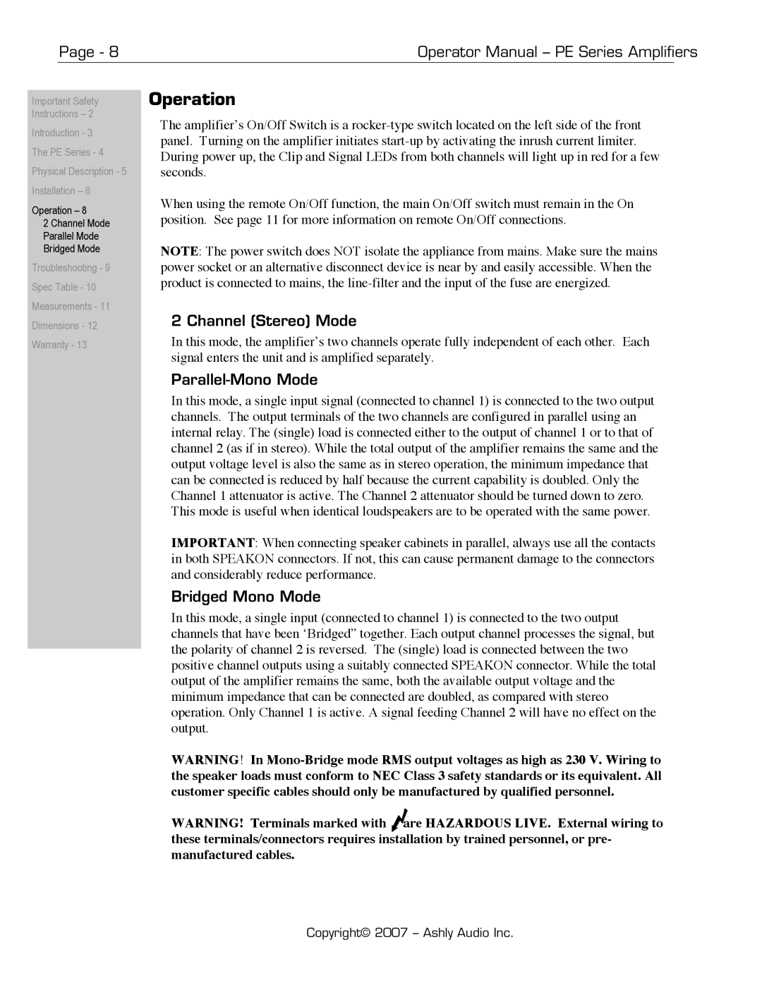
The Ashly PE Series is renowned in the audio industry for its exceptional performance, versatility, and reliability. Designed for professional audio applications, the PE Series amplifiers deliver powerful sound quality, making them suitable for live sound, installations, and event productions.One of the standout features of the Ashly PE Series is its advanced Class D amplification technology. This technology not only enhances efficiency but also ensures that the amplifiers remain lightweight and manageable, making them an ideal choice for touring and mobile setups. The PE Series offers a range of power options, from modest wattage to high-output models, catering to various needs and scenarios.
Another significant characteristic of the PE Series is the incorporation of Ashly's proprietary DSP capabilities. The built-in digital signal processing allows users to optimize audio performance through customizable equalization, limiting, and crossover functions. This flexibility helps users fine-tune their sound systems to achieve the desired audio quality, whether in a small venue or a large concert environment.
The PE Series amplifiers also feature a rugged and durable design, built to withstand the rigors of touring and installation. With sealed enclosures, high-quality components, and a robust cooling system, these amplifiers are engineered for longevity and consistent performance. The intuitive front panel controls and clear LED indicators provide users with essential information at a glance, facilitating ease of use for sound engineers and operators.
Connectivity is another strength of the Ashly PE Series. The amplifiers come equipped with multiple input options, including balanced XLR and TRS connectors, enabling seamless integration with various audio sources. Additionally, the units include Speakon and binding post output connectors, ensuring compatibility with a broad range of loudspeakers.
In summary, the Ashly PE Series amplifiers embody the perfect blend of power, flexibility, and durability. With advanced Class D technology, integrated DSP capabilities, and robust construction, these amplifiers meet the demands of diverse audio environments. Whether for live events, installations, or studio applications, the Ashly PE Series stands out as a reliable choice for professionals seeking high-quality audio performance.

